
Ever wanted to plug in servos like LEGO – no messy jumper wire jungle? The Sensor Shield V5.0 makes that happen by giving you labeled 3-pin ports for Signal, 5V, and GND. In this beginner test, you will drive 10 servos from one Arduino using a simple sweep pattern. You will instantly see if your ports, power rail, and signal routing are correct.
This tutorial uses a short sketch that attaches 10 servos to 10 digital pins and moves them together. First, the code centers all servos at 90°, then it flips them to 0°, then to 180°. That repeated motion makes problems easy to spot, like one servo not moving, jittering, or moving in the wrong direction. It’s a clean “does my shield setup work?” test before you build a robot arm or animatronics rig.
The key idea is that the shield mainly improves wiring and organization, not raw power. Servos can draw a lot of current, so you must plan power correctly when you scale to 10 units. Once you understand the ports and power strategy, the shield becomes a fast way to prototype multi-servo builds without confusion.
Why Build?
This test is the fastest way to check if your shield ports work.
If one port is wrong, one servo will not match the group motion.
You can then swap only that one servo to confirm the real cause.
This saves time before you add brackets, horns, and linkages.
It also prevents breaking parts from sudden wrong movement.
It also helps you validate your power setup early.
Servos often jitter or reset when the 5V rail is weak.
With ten servos moving together, a weak supply shows up quickly.
You will notice dips, random twitching, or the Arduino resetting.
That feedback is hard to miss, which is good for beginners.
This guide also gives you a repeatable “known good” baseline.
When a later project fails, you can rerun this test in minutes.
If it works again, your servo driver path is likely fine.
Then you can focus on sensors, code logic, or mechanics next.
That keeps troubleshooting simple and less stressful.
What You’ll Learn
- Shield ports – how the S / 5V / GND rows simplify servo wiring.
- Pin mapping – how each port’s “S” line links to an Arduino pin.
- Multi-servo setup – attaching ten servos using an array and loop.
- Safe start – why centering at 90° reduces surprise movement.
- Direction test – how 0° and 180° checks both ends of travel.
- Power rules – why ten servos need a strong 5V rail.
- Shared ground – why Arduino GND must match servo supply GND.
- Fault spotting – how to tell bad wiring from a bad servo fast.
- Next upgrades – offsets, smooth ramps, and timed sequences.
What You'll Need
Fritzing Diagram
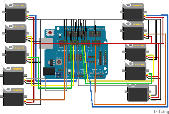
Wiring Connection
Servo signal pins
- Servo 1 → D2
- Servo 2 → D5
- Servo 3 → D6
- Servo 4 → D7
- Servo 5 → D8
- Servo 6 → D9
- Servo 7 → D10
- Servo 8 → D11
- Servo 9 → D12
- Servo 10 → D13
Sample Code
#include <Servo.h>

Servo servos[10];

int servoPins[10] = {
  2, 5, 6, 7, 8, 9, 10, 11, 12, 13
};

void setup() {
  for (int i = 0; i < 10; i++) {
    servos[i].attach(servoPins[i]);
    servos[i].write(90);
  }
}

void loop() {
  for (int i = 0; i < 10; i++) {
    servos[i].write(0);
  }
  delay(1000);

  for (int i = 0; i < 10; i++) {
    servos[i].write(180);
  }
  delay(1000);
}
How It Works
The code creates Servo servos[10] so control stays organized.
It also lists ten pins: 2, 5, 6, 7, 8, 9, 10, 11, 12, 13.
In setup(), each servo attaches to one pin from that list.
Right after attach, it writes 90° to center every servo.
This gives a clear starting pose for your test.
In the loop, the first pass sets all servos to 0°.
The delay(1000) gives time for every servo to reach the angle.
Next, the second pass sets all servos to 180°.
Another delay keeps motion easy to see and easy to compare.
Because all servos move together, mismatches stand out instantly.
Sensor Shield V5.0 makes the physical wiring much easier.
Each servo plugs into a 3-pin header: S, 5V, and GND.
The S pin goes to the Arduino signal pin used in your sketch.
The 5V/GND pins feed power, ideally from an external 5V source.
Always tie external GND to Arduino GND for stable signals.
Applications & Extensions
Use this as an incoming test for every new servo or shield.
It helps you confirm each port works before you build a robot.
It also helps you sort servos by strength and smoothness.
If one jitters here, it will be worse under real load later.
Fix it now, while the setup is still simple.
After the test, make motion smoother and safer for mechanics.
Add per-servo offsets so “90°” matches true center on each joint.
Then replace hard jumps with small steps for smooth movement.
You can also move one servo at a time to confirm pin order.
That lowers current spikes and keeps testing calmer.
Next, build real projects on the same shield layout.
Use a joystick to control a pan-tilt head with two servos.
Use buttons to trigger poses for props and small animatronics.
Add a kill switch for servo power during setup and tuning.
When the rig grows, use a stronger 5V rail and thicker wires.
Watch the Full Demo Video
Here’s the Sensor Shield V5.0.