
Creating a parallel circuit using copper foil tape and a coin cell battery is a simple and educational. It will introduce you to basic electronics. This setup allows you to explore how parallel circuits function, as it distributes current evenly across multiple components.
It starts by laying down two strips of copper tape on a flat surface. It serves as the positive and negative paths. Place your LEDs across these paths, ensuring each LED connects to both strips. Next, attach the coin cell battery to the copper tape, aligning the positive and negative terminals with the corresponding strips. Secure the connections with tape for stability. If the setup is done, LED will light up.
By using a coin cell battery, you can observe how current is distributed across different components. This straightforward project offers a solid foundation for understanding electronics and the role of parallel circuits in various devices.
Components
Connections:
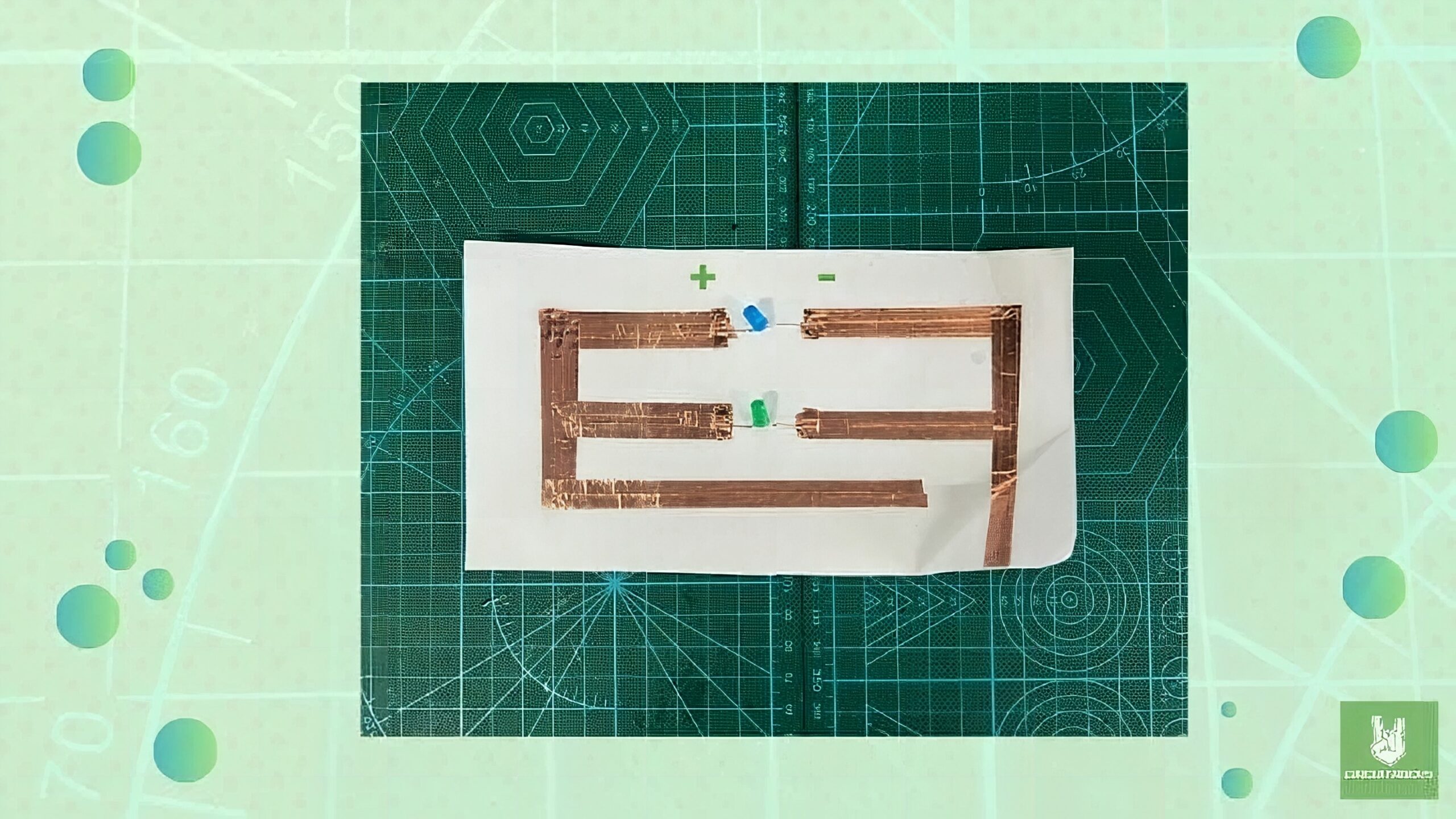
To create connections in the circuit shown in the image:
- Identify the Paths:
The paths should run from the battery connection points to the LEDs.
- Connect LED:
Ensure that each LED’s positive leg (anode) is connected to the positive copper strip, and the negative leg (cathode) is connected to the negative strip.
- Coin Battery:
Fold the paper in such a way that the positive and negative copper tape strips align with the corresponding terminals of the coin cell battery.
QUICK LINK
Frequently Asked Questions
What does this Simple Parallel Circuit Using Copper Tape tutorial cover?
Creating a parallel circuit using copper foil tape and a coin cell battery is a simple and educational.
What's the working voltage of the Simple Parallel Circuit Using Copper Tape?
Check the Sample Code section for the exact pinout — most maker-grade sensors run on 3.3V or 5V. Wire VCC to the matching rail, GND common with your MCU, data to a digital or analog pin.
Why does the Simple Parallel Circuit Using Copper Tape read garbage or saturated values?
Three usual causes: wrong voltage rail, missing pull-up resistor on I2C lines (4.7k–10k to VCC), or a floating data pin. Double-check wiring against the diagram, then probe with a multimeter.