// jomarOctober 10, 2025updated July 7, 20262 min read
Have you ever wondered how lights on a staircase can be switched on or off from both ends? That’s the idea behind a two-way switch circuit! In this project, we’ll make a mini 3D staircase that shows how this type of wiring works. It’s a simple, hands-on way to understand how two switches can control one light from different places.
The 3D Two-way Switch isn’t just about lighting up LEDs. It’s about understanding the logic behind switch connections and circuit flow. By recreating this familiar household system, learners can visualize how electrical control can exist in two different locations while maintaining a single circuit output. It’s a great starting point for anyone curious about how home wiring works or looking to enhance their basic electronics knowledge through a hands-on build.
What makes it even better is the 3D look! The staircase adds a creative touch, making the project more exciting and interactive. Whether you’re doing a classroom demo or a DIY hobby build, this project is a great way to mix creativity with electronics – and it’s something you’ll be proud to show off!
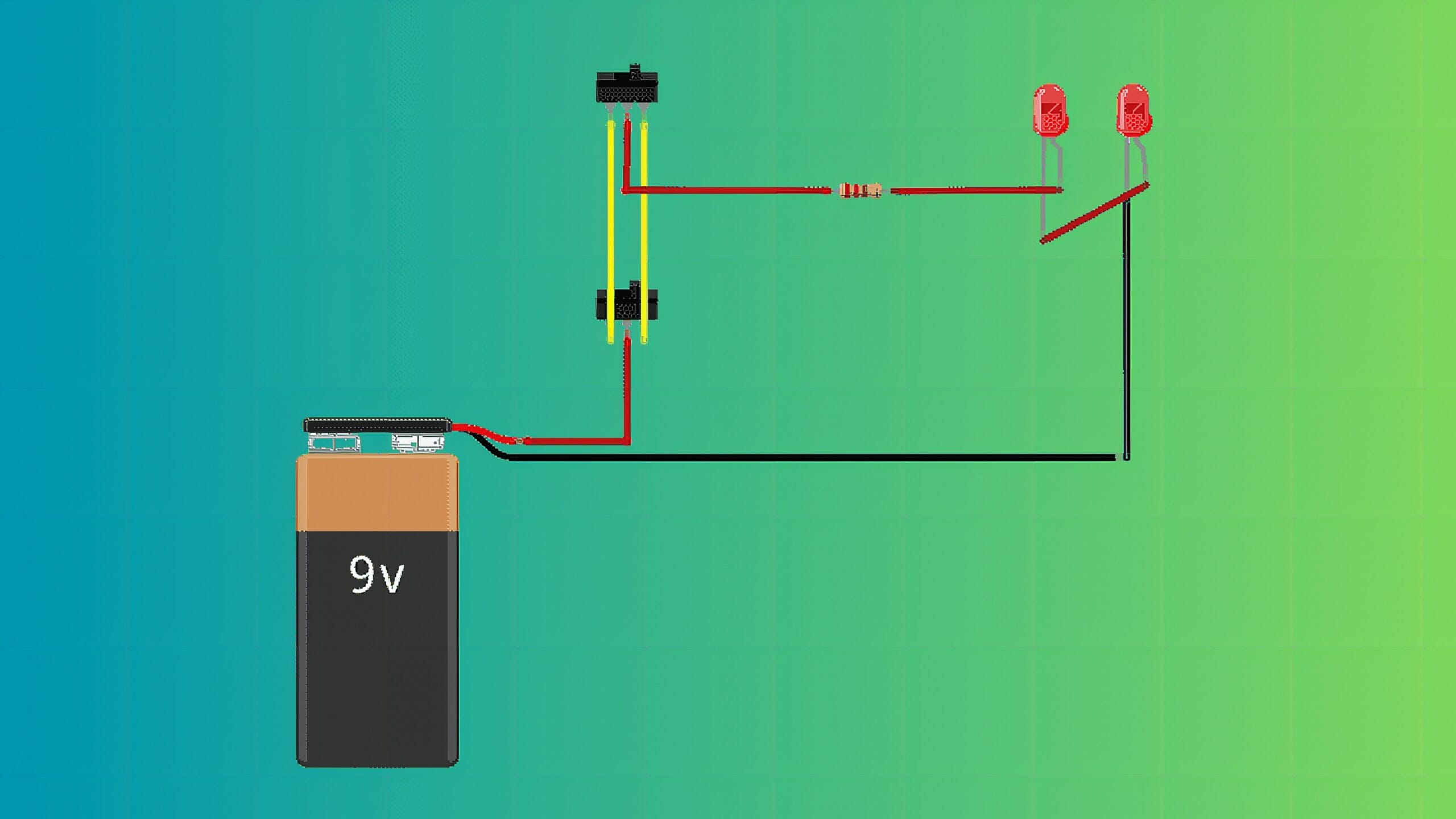
Circuit Diagram
How it Works?
This 3D Two-Way Switch uses two SPDT (Single Pole Double Throw) switches to demonstrate a real-world two-way switching system – similar to how you can turn a staircase light on or off from either the top or the bottom.
In this setup, the two 5mm LEDs act as the light source. Both LEDs share the same ground and same anode line, which connects to the switches. A 150Ω resistor limits the current to protect the LEDs, while a 9V power supply provides the voltage needed for operation.
When either SPDT switch changes position, it redirects the electrical path. One position completes the circuit, turning the LEDs ON; the other breaks the path, turning them OFF. This switching logic makes the circuit behave as if both switches “communicate,” allowing control of the light from two different points – just like in a real staircase lighting system.
Applications and Extensions
The 3D Two-Way Switch Staircase isn’t just an experiment – it’s a foundation for future innovation. Beyond lighting systems, this setup can evolve into smart automation projects using relays or microcontrollers like Arduino or ESP32. You can also integrate motion sensors or wireless control to make it part of a complete IoT-based smart home model.
As a learning tool, this 3D version continues to inspire creativity. It’s perfect for classroom demos, exhibits, or hobby projects that encourage students to connect theory with real-world applications.
Have you ever wondered how lights on a staircase can be switched on or off from both ends? That’s the idea behind a two-way switch circuit! In this project, we’ll make a mini 3D staircase that shows how this type of wiring works.
What filament works best for the 3D Two-way Switch build?
PLA for cosmetic/indoor parts (cheap, easy to print). PETG for parts that flex or live near heat. ABS only if you have an enclosure — it warps in open air.
What slicer settings work for this build?
0.2mm layer height, 20% gyroid infill, 3 perimeters, supports only where the model needs them. PLA: 200°C nozzle, 60°C bed. 50-60 mm/s on most desktop FDMs.
Jomar Zabala builds robots, line-followers, and microcontroller projects at Circuitrocks. He writes hands-on guides covering sensors, motor control, and embedded systems — the kind of bench-tested walkthroughs he wishes existed when he started with Arduino and ESP32.