
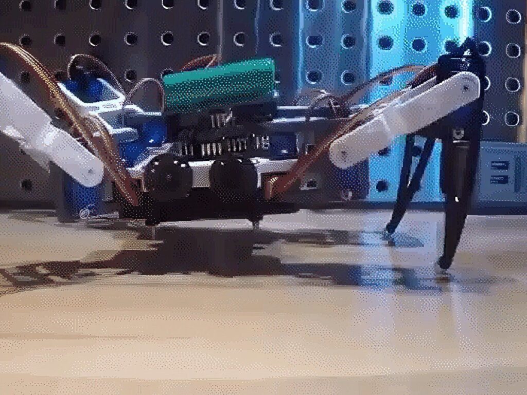
Introducing Spidey our (4 Legs spider) Quadruped Robot 3D printed
This robot works wonderfully, you are going to surely complete your project with a nice walking robot in as little as 2 hours.
Parts used for this project:
Parts in this build
The GPIO expansion shield specifically designed for Arduino UNO-type boards. This shield greatly expands the GPIO resources to 36 pins in total, including 14 digital pins, 6 analog pins and 16 I2C pins. Because of this we can easily connect the 8 servo motor to our arduino directly.
A quadruped robot is a robot with four legs. There are any number of ways a four-legged robot can be designed. The robot we will be building in this Instructable has four legs arranged symmetrically around the body.
Let’s get started!
upload the PCB layout image file, you should download the zip file would be better.
You can come here for more information about PCB DIY. http://regishsu.blogspot.tw/search/label/0.SpiderR…
******************************************************************
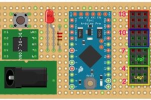
Refer to the schematics file, and place all components like the pictures. you can make the board as small as passable.
The main-board that the last one picture is the newest version, just for you reference.
Here are some tips while you are going to building the PCB:
1. Be sure the output voltage of DC-DC module should be 5v before mount to the perfboard.
2. The servos consume a lot of power, almost 3A in full loading condition. Please use more thick wire for “power” and ground” traces.
3. Do the “open/short” test with the multi-meter for your PCB when you finish the soldering, that is the important process.
4. Using the female pin header instead of solder the modules(Arduino, DC-DC) on the perfboard directly
5. The LED will be on while the “Switch” turns off. Why I design this way is because I would like to check the power source is ok or not when I plug in the power source like battery or something else, it is a simple way for protection..
6. While you see the LED turns on after connect the 12v battery to the board, congratulation!
Next step!
Test the Main-board
Test process:
- Don’t plug the DC-DC and Arduino Pro Mini into the main-board
- connect the battery to the 12v-Jack of main-board
- Check the LED, if LED turns on, that is a good start.
- Push the POWER-Switch, the LED should be off. Using the multi-meter to check all of +5V and GND pins are correct. Push the POWER-Switch back to turn off the power, the LED turns on.
- Plug the DC-DC and Arduino Pro Mini into the main-board
- Push the POWER-Switch, the LED turns off, but the LED of Arduino Pro Mini turns on
Then power off, and connect a servo to the first row of Leg1 connectors of main-board(pin2 of Arduino)
upload the “servo_test” code to Arduino and you will see the servo sweeps from 0 – 180 degree.
If you are here without any problem, that is a great progress!
Next Step!
Assemble the body!
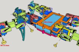
Put the battery between the upper body case and lower body case with 4 screws(M3x25mm)
And, install all of servos with legs parts, one leg comes with 3 servos and 4 screws(M1.6x3mm, or glue it anyway)
Notes: 1. Connect to all parts with screws and servos, but do not install the servo rocker arm in this step 2. Be sure the leg direction
Place the main-board onto the body-case and use the polymer clay to fix it.
And then, refer to the picture, follow the pin number which mark by pink color to connect all servo wire to the main-board, and green color is present the signal direction of servo wire, yellow connect to “S”, red to “+”, brown to “-“.
Be sure the servo of legs should match the pin number of main-board and leg direction, otherwise, the legs will get crazy…
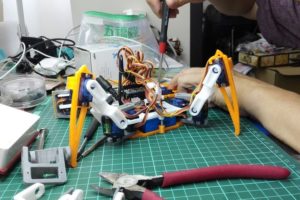
connect all of legs to the body, and check all servos and joints are move smoothly.
This is an important procedure, the install procedure:
1. upload the “legs_init” code to Arduino to activate the servos
2. place the legs as the position shows the picture 1, and install the servo rocker arm with screws.
3. tighten all of the screw
The exciting part!
Let’s upload the “spider_open_v1” code to Arduino to make it moves!
Please download and install the lib FlexiTimer2 first before do compile the code, http://playground.arduino.cc/Main/FlexiTimer2
you will see the action as following
- stand up, wait 2 sec
- step forward 5 steps, wait 2 sec
- backward 5 steps, wait 2 sec
- turn right, wait 2 sec
- turn left, wait 2 sec
- wave the hand,, wait 2 sec
- shake the hand, wait 2 sec
- sit down, wait 2 sec
- back to 1
Enjoy!
PS. the spider_open_v3 is add an interesting movement of “body dancing”
you can add more special feature like change the move speed dynamically with remote control, that will let your robot more attractive.
// Locate the initial position of legs // RegisHsu 2015-09-09 #include <Servo.h> Servo servo[4][3]; //define servos' ports
const int servo_pin[4][3] = { {2, 3, 4}, {5, 6, 7}, {8, 9, 10}, {11, 12, 13} }; void setup()
{ //initialize all servos for (int i = 0; i < 4; i++) { for (int j = 0; j < 3; j++) { servo[i][j].attach(servo_pin[i][j]); delay(20); } }
} void loop(void)
{ for (int i = 0; i < 4; i++) { for (int j = 0; j < 3; j++) { servo[i][j].write(90); delay(20); } }
}
#include <Servo.h> //to define and control servos
#include <FlexiTimer2.h>//to set a timer to manage all servos
/* Servos --------------------------------------------------------------------*/
//define 12 servos for 4 legs
Servo servo[4][3];
//define servos' ports
const int servo_pin[4][3] = { {2, 3, 4}, {5, 6, 7}, {8, 9, 10}, {11, 12, 13} };
/* Size of the robot ---------------------------------------------------------*/
const float length_a = 55;
const float length_b = 77.5;
const float length_c = 27.5;
const float length_side = 71;
const float z_absolute = -28;
/* Constants for movement ----------------------------------------------------*/
const float z_default = -50, z_up = -30, z_boot = z_absolute;
const float x_default = 62, x_offset = 0;
const float y_start = 0, y_step = 40;
/* variables for movement ----------------------------------------------------*/
volatile float site_now[4][3]; //real-time coordinates of the end of each leg
volatile float site_expect[4][3]; //expected coordinates of the end of each leg
float temp_speed[4][3]; //each axis' speed, needs to be recalculated before each movement
float move_speed; //movement speed
float speed_multiple = 1; //movement speed multiple
const float spot_turn_speed = 4;
const float leg_move_speed = 8;
const float body_move_speed = 3;
const float stand_seat_speed = 1;
volatile int rest_counter; //+1/0.02s, for automatic rest
//functions' parameter
const float KEEP = 255;
//define PI for calculation
const float pi = 3.1415926;
/* Constants for turn --------------------------------------------------------*/
//temp length
const float temp_a = sqrt(pow(2 * x_default + length_side, 2) + pow(y_step, 2));
const float temp_b = 2 * (y_start + y_step) + length_side;
const float temp_c = sqrt(pow(2 * x_default + length_side, 2) + pow(2 * y_start + y_step + length_side, 2));
const float temp_alpha = acos((pow(temp_a, 2) + pow(temp_b, 2) - pow(temp_c, 2)) / 2 / temp_a / temp_b);
//site for turn
const float turn_x1 = (temp_a - length_side) / 2;
const float turn_y1 = y_start + y_step / 2;
const float turn_x0 = turn_x1 - temp_b * cos(temp_alpha);
const float turn_y0 = temp_b * sin(temp_alpha) - turn_y1 - length_side;
/* ---------------------------------------------------------------------------*/ /* - setup function ---------------------------------------------------------------------------*/
void setup()
{ //start serial for debug Serial.begin(115200); Serial.println("Robot starts initialization"); //initialize default parameter set_site(0, x_default - x_offset, y_start + y_step, z_boot); set_site(1, x_default - x_offset, y_start + y_step, z_boot); set_site(2, x_default + x_offset, y_start, z_boot); set_site(3, x_default + x_offset, y_start, z_boot); for (int i = 0; i < 4; i++) { for (int j = 0; j < 3; j++) { site_now[i][j] = site_expect[i][j]; } } //start servo service FlexiTimer2::set(20, servo_service); FlexiTimer2::start(); Serial.println("Servo service started"); //initialize servos servo_attach(); Serial.println("Servos initialized"); Serial.println("Robot initialization Complete");
} void servo_attach(void)
{ for (int i = 0; i < 4; i++) { for (int j = 0; j < 3; j++) { delay(500); servo[i][j].attach(servo_pin[i][j]); delay(10); } }
} void servo_detach(void)
{ for (int i = 0; i < 4; i++) { for (int j = 0; j < 3; j++) { servo[i][j].detach(); delay(100); } }
}
/* - loop function ---------------------------------------------------------------------------*/
void loop()
{ Serial.println("Stand"); stand(); delay(2000); Serial.println("Step forward"); step_forward(1000); delay(2000); Serial.println("Step back"); step_back(5); delay(2000); Serial.println("Turn left"); turn_left(5); delay(2000); Serial.println("Turn right"); turn_right(5); delay(2000); Serial.println("Hand wave"); hand_wave(5); delay(5000); Serial.println("Hand wave"); hand_shake(3); delay(2000); Serial.println("Sit"); sit(); delay(5000); while(true){} } /* - sit - blocking function ---------------------------------------------------------------------------*/
void sit(void)
{ move_speed = stand_seat_speed; for (int leg = 0; leg < 4; leg++) { set_site(leg, KEEP, KEEP, z_boot); } wait_all_reach();
} /* - stand - blocking function ---------------------------------------------------------------------------*/
void stand(void)
{ move_speed = stand_seat_speed; for (int leg = 0; leg < 4; leg++) { set_site(leg, KEEP, KEEP, z_default); } wait_all_reach();
} /* - spot turn to left - blocking function - parameter step steps wanted to turn ---------------------------------------------------------------------------*/
void turn_left(unsigned int step)
{ move_speed = spot_turn_speed; while (step-- > 0) { if (site_now[3][1] == y_start) { //leg 3&1 move set_site(3, x_default + x_offset, y_start, z_up); wait_all_reach(); set_site(0, turn_x1 - x_offset, turn_y1, z_default); set_site(1, turn_x0 - x_offset, turn_y0, z_default); set_site(2, turn_x1 + x_offset, turn_y1, z_default); set_site(3, turn_x0 + x_offset, turn_y0, z_up); wait_all_reach(); set_site(3, turn_x0 + x_offset, turn_y0, z_default); wait_all_reach(); set_site(0, turn_x1 + x_offset, turn_y1, z_default); set_site(1, turn_x0 + x_offset, turn_y0, z_default); set_site(2, turn_x1 - x_offset, turn_y1, z_default); set_site(3, turn_x0 - x_offset, turn_y0, z_default); wait_all_reach(); set_site(1, turn_x0 + x_offset, turn_y0, z_up); wait_all_reach(); set_site(0, x_default + x_offset, y_start, z_default); set_site(1, x_default + x_offset, y_start, z_up); set_site(2, x_default - x_offset, y_start + y_step, z_default); set_site(3, x_default - x_offset, y_start + y_step, z_default); wait_all_reach(); set_site(1, x_default + x_offset, y_start, z_default); wait_all_reach(); } else { //leg 0&2 move set_site(0, x_default + x_offset, y_start, z_up); wait_all_reach(); set_site(0, turn_x0 + x_offset, turn_y0, z_up); set_site(1, turn_x1 + x_offset, turn_y1, z_default); set_site(2, turn_x0 - x_offset, turn_y0, z_default); set_site(3, turn_x1 - x_offset, turn_y1, z_default); wait_all_reach(); set_site(0, turn_x0 + x_offset, turn_y0, z_default); wait_all_reach(); set_site(0, turn_x0 - x_offset, turn_y0, z_default); set_site(1, turn_x1 - x_offset, turn_y1, z_default); set_site(2, turn_x0 + x_offset, turn_y0, z_default); set_site(3, turn_x1 + x_offset, turn_y1, z_default); wait_all_reach(); set_site(2, turn_x0 + x_offset, turn_y0, z_up); wait_all_reach(); set_site(0, x_default - x_offset, y_start + y_step, z_default); set_site(1, x_default - x_offset, y_start + y_step, z_default); set_site(2, x_default + x_offset, y_start, z_up); set_site(3, x_default + x_offset, y_start, z_default); wait_all_reach(); set_site(2, x_default + x_offset, y_start, z_default); wait_all_reach(); } }
} /* - spot turn to right - blocking function - parameter step steps wanted to turn ---------------------------------------------------------------------------*/
void turn_right(unsigned int step)
{ move_speed = spot_turn_speed; while (step-- > 0) { if (site_now[2][1] == y_start) { //leg 2&0 move set_site(2, x_default + x_offset, y_start, z_up); wait_all_reach(); set_site(0, turn_x0 - x_offset, turn_y0, z_default); set_site(1, turn_x1 - x_offset, turn_y1, z_default); set_site(2, turn_x0 + x_offset, turn_y0, z_up); set_site(3, turn_x1 + x_offset, turn_y1, z_default); wait_all_reach(); set_site(2, turn_x0 + x_offset, turn_y0, z_default); wait_all_reach(); set_site(0, turn_x0 + x_offset, turn_y0, z_default); set_site(1, turn_x1 + x_offset, turn_y1, z_default); set_site(2, turn_x0 - x_offset, turn_y0, z_default); set_site(3, turn_x1 - x_offset, turn_y1, z_default); wait_all_reach(); set_site(0, turn_x0 + x_offset, turn_y0, z_up); wait_all_reach(); set_site(0, x_default + x_offset, y_start, z_up); set_site(1, x_default + x_offset, y_start, z_default); set_site(2, x_default - x_offset, y_start + y_step, z_default); set_site(3, x_default - x_offset, y_start + y_step, z_default); wait_all_reach(); set_site(0, x_default + x_offset, y_start, z_default); wait_all_reach(); } else { //leg 1&3 move set_site(1, x_default + x_offset, y_start, z_up); wait_all_reach(); set_site(0, turn_x1 + x_offset, turn_y1, z_default); set_site(1, turn_x0 + x_offset, turn_y0, z_up); set_site(2, turn_x1 - x_offset, turn_y1, z_default); set_site(3, turn_x0 - x_offset, turn_y0, z_default); wait_all_reach(); set_site(1, turn_x0 + x_offset, turn_y0, z_default); wait_all_reach(); set_site(0, turn_x1 - x_offset, turn_y1, z_default); set_site(1, turn_x0 - x_offset, turn_y0, z_default); set_site(2, turn_x1 + x_offset, turn_y1, z_default); set_site(3, turn_x0 + x_offset, turn_y0, z_default); wait_all_reach(); set_site(3, turn_x0 + x_offset, turn_y0, z_up); wait_all_reach(); set_site(0, x_default - x_offset, y_start + y_step, z_default); set_site(1, x_default - x_offset, y_start + y_step, z_default); set_site(2, x_default + x_offset, y_start, z_default); set_site(3, x_default + x_offset, y_start, z_up); wait_all_reach(); set_site(3, x_default + x_offset, y_start, z_default); wait_all_reach(); } }
} /* - go forward - blocking function - parameter step steps wanted to go ---------------------------------------------------------------------------*/
void step_forward(unsigned int step)
{ move_speed = leg_move_speed; while (step-- > 0) { if (site_now[2][1] == y_start) { //leg 2&1 move set_site(2, x_default + x_offset, y_start, z_up); wait_all_reach(); set_site(2, x_default + x_offset, y_start + 2 * y_step, z_up); wait_all_reach(); set_site(2, x_default + x_offset, y_start + 2 * y_step, z_default); wait_all_reach(); move_speed = body_move_speed; set_site(0, x_default + x_offset, y_start, z_default); set_site(1, x_default + x_offset, y_start + 2 * y_step, z_default); set_site(2, x_default - x_offset, y_start + y_step, z_default); set_site(3, x_default - x_offset, y_start + y_step, z_default); wait_all_reach(); move_speed = leg_move_speed; set_site(1, x_default + x_offset, y_start + 2 * y_step, z_up); wait_all_reach(); set_site(1, x_default + x_offset, y_start, z_up); wait_all_reach(); set_site(1, x_default + x_offset, y_start, z_default); wait_all_reach(); } else { //leg 0&3 move set_site(0, x_default + x_offset, y_start, z_up); wait_all_reach(); set_site(0, x_default + x_offset, y_start + 2 * y_step, z_up); wait_all_reach(); set_site(0, x_default + x_offset, y_start + 2 * y_step, z_default); wait_all_reach(); move_speed = body_move_speed; set_site(0, x_default - x_offset, y_start + y_step, z_default); set_site(1, x_default - x_offset, y_start + y_step, z_default); set_site(2, x_default + x_offset, y_start, z_default); set_site(3, x_default + x_offset, y_start + 2 * y_step, z_default); wait_all_reach(); move_speed = leg_move_speed; set_site(3, x_default + x_offset, y_start + 2 * y_step, z_up); wait_all_reach(); set_site(3, x_default + x_offset, y_start, z_up); wait_all_reach(); set_site(3, x_default + x_offset, y_start, z_default); wait_all_reach(); } }
} /* - go back - blocking function - parameter step steps wanted to go ---------------------------------------------------------------------------*/
void step_back(unsigned int step)
{ move_speed = leg_move_speed; while (step-- > 0) { if (site_now[3][1] == y_start) { //leg 3&0 move set_site(3, x_default + x_offset, y_start, z_up); wait_all_reach(); set_site(3, x_default + x_offset, y_start + 2 * y_step, z_up); wait_all_reach(); set_site(3, x_default + x_offset, y_start + 2 * y_step, z_default); wait_all_reach(); move_speed = body_move_speed; set_site(0, x_default + x_offset, y_start + 2 * y_step, z_default); set_site(1, x_default + x_offset, y_start, z_default); set_site(2, x_default - x_offset, y_start + y_step, z_default); set_site(3, x_default - x_offset, y_start + y_step, z_default); wait_all_reach(); move_speed = leg_move_speed; set_site(0, x_default + x_offset, y_start + 2 * y_step, z_up); wait_all_reach(); set_site(0, x_default + x_offset, y_start, z_up); wait_all_reach(); set_site(0, x_default + x_offset, y_start, z_default); wait_all_reach(); } else { //leg 1&2 move set_site(1, x_default + x_offset, y_start, z_up); wait_all_reach(); set_site(1, x_default + x_offset, y_start + 2 * y_step, z_up); wait_all_reach(); set_site(1, x_default + x_offset, y_start + 2 * y_step, z_default); wait_all_reach(); move_speed = body_move_speed; set_site(0, x_default - x_offset, y_start + y_step, z_default); set_site(1, x_default - x_offset, y_start + y_step, z_default); set_site(2, x_default + x_offset, y_start + 2 * y_step, z_default); set_site(3, x_default + x_offset, y_start, z_default); wait_all_reach(); move_speed = leg_move_speed; set_site(2, x_default + x_offset, y_start + 2 * y_step, z_up); wait_all_reach(); set_site(2, x_default + x_offset, y_start, z_up); wait_all_reach(); set_site(2, x_default + x_offset, y_start, z_default); wait_all_reach(); } }
} // add by RegisHsu void body_left(int i)
{ set_site(0, site_now[0][0] + i, KEEP, KEEP); set_site(1, site_now[1][0] + i, KEEP, KEEP); set_site(2, site_now[2][0] - i, KEEP, KEEP); set_site(3, site_now[3][0] - i, KEEP, KEEP); wait_all_reach();
} void body_right(int i)
{ set_site(0, site_now[0][0] - i, KEEP, KEEP); set_site(1, site_now[1][0] - i, KEEP, KEEP); set_site(2, site_now[2][0] + i, KEEP, KEEP); set_site(3, site_now[3][0] + i, KEEP, KEEP); wait_all_reach();
} void hand_wave(int i)
{ float x_tmp; float y_tmp; float z_tmp; move_speed = 1; if (site_now[3][1] == y_start) { body_right(15); x_tmp = site_now[2][0]; y_tmp = site_now[2][1]; z_tmp = site_now[2][2]; move_speed = body_move_speed; for (int j = 0; j < i; j++) { set_site(2, turn_x1, turn_y1, 50); wait_all_reach(); set_site(2, turn_x0, turn_y0, 50); wait_all_reach(); } set_site(2, x_tmp, y_tmp, z_tmp); wait_all_reach(); move_speed = 1; body_left(15); } else { body_left(15); x_tmp = site_now[0][0]; y_tmp = site_now[0][1]; z_tmp = site_now[0][2]; move_speed = body_move_speed; for (int j = 0; j < i; j++) { set_site(0, turn_x1, turn_y1, 50); wait_all_reach(); set_site(0, turn_x0, turn_y0, 50); wait_all_reach(); } set_site(0, x_tmp, y_tmp, z_tmp); wait_all_reach(); move_speed = 1; body_right(15); }
} void hand_shake(int i)
{ float x_tmp; float y_tmp; float z_tmp; move_speed = 1; if (site_now[3][1] == y_start) { body_right(15); x_tmp = site_now[2][0]; y_tmp = site_now[2][1]; z_tmp = site_now[2][2]; move_speed = body_move_speed; for (int j = 0; j < i; j++) { set_site(2, x_default - 30, y_start + 2 * y_step, 55); wait_all_reach(); set_site(2, x_default - 30, y_start + 2 * y_step, 10); wait_all_reach(); } set_site(2, x_tmp, y_tmp, z_tmp); wait_all_reach(); move_speed = 1; body_left(15); } else { body_left(15); x_tmp = site_now[0][0]; y_tmp = site_now[0][1]; z_tmp = site_now[0][2]; move_speed = body_move_speed; for (int j = 0; j < i; j++) { set_site(0, x_default - 30, y_start + 2 * y_step, 55); wait_all_reach(); set_site(0, x_default - 30, y_start + 2 * y_step, 10); wait_all_reach(); } set_site(0, x_tmp, y_tmp, z_tmp); wait_all_reach(); move_speed = 1; body_right(15); }
} /* - microservos service /timer interrupt function/50Hz - when set site expected,this function move the end point to it in a straight line - temp_speed[4][3] should be set before set expect site,it make sure the end point move in a straight line,and decide move speed. ---------------------------------------------------------------------------*/
void servo_service(void)
{ sei(); static float alpha, beta, gamma; for (int i = 0; i < 4; i++) { for (int j = 0; j < 3; j++) { if (abs(site_now[i][j] - site_expect[i][j]) >= abs(temp_speed[i][j])) site_now[i][j] += temp_speed[i][j]; else site_now[i][j] = site_expect[i][j]; } cartesian_to_polar(alpha, beta, gamma, site_now[i][0], site_now[i][1], site_now[i][2]); polar_to_servo(i, alpha, beta, gamma); } rest_counter++;
} /* - set one of end points' expect site - this founction will set temp_speed[4][3] at same time - non - blocking function ---------------------------------------------------------------------------*/
void set_site(int leg, float x, float y, float z)
{ float length_x = 0, length_y = 0, length_z = 0; if (x!= KEEP) length_x = x - site_now[leg][0]; if (y!= KEEP) length_y = y - site_now[leg][1]; if (z!= KEEP) length_z = z - site_now[leg][2]; float length = sqrt(pow(length_x, 2) + pow(length_y, 2) + pow(length_z, 2)); temp_speed[leg][0] = length_x / length * move_speed * speed_multiple; temp_speed[leg][1] = length_y / length * move_speed * speed_multiple; temp_speed[leg][2] = length_z / length * move_speed * speed_multiple; if (x!= KEEP) site_expect[leg][0] = x; if (y!= KEEP) site_expect[leg][1] = y; if (z!= KEEP) site_expect[leg][2] = z;
} /* - wait one of end points move to expect site - blocking function ---------------------------------------------------------------------------*/
void wait_reach(int leg)
{ while (1) if (site_now[leg][0] == site_expect[leg][0]) if (site_now[leg][1] == site_expect[leg][1]) if (site_now[leg][2] == site_expect[leg][2]) break;
} /* - wait all of end points move to expect site - blocking function ---------------------------------------------------------------------------*/
void wait_all_reach(void)
{ for (int i = 0; i < 4; i++) wait_reach(i);
} /* - trans site from cartesian to polar - mathematical model 2/2 ---------------------------------------------------------------------------*/
void cartesian_to_polar(volatile float &alpha, volatile float &beta, volatile float &gamma, volatile float x, volatile float y, volatile float z)
{ //calculate w-z degree float v, w; w = (x >= 0? 1: -1) * (sqrt(pow(x, 2) + pow(y, 2))); v = w - length_c; alpha = atan2(z, v) + acos((pow(length_a, 2) - pow(length_b, 2) + pow(v, 2) + pow(z, 2)) / 2 / length_a / sqrt(pow(v, 2) + pow(z, 2))); beta = acos((pow(length_a, 2) + pow(length_b, 2) - pow(v, 2) - pow(z, 2)) / 2 / length_a / length_b); //calculate x-y-z degree gamma = (w >= 0)? atan2(y, x): atan2(-y, -x); //trans degree pi->180 alpha = alpha / pi * 180; beta = beta / pi * 180; gamma = gamma / pi * 180;
} /* - trans site from polar to microservos - mathematical model map to fact - the errors saved in eeprom will be add ---------------------------------------------------------------------------*/
void polar_to_servo(int leg, float alpha, float beta, float gamma)
{ if (leg == 0) { alpha = 90 - alpha; beta = beta; gamma += 90; } else if (leg == 1) { alpha += 90; beta = 180 - beta; gamma = 90 - gamma; } else if (leg == 2) { alpha += 90; beta = 180 - beta; gamma = 90 - gamma; } else if (leg == 3) { alpha = 90 - alpha; beta = beta; gamma += 90; } servo[leg][0].write(alpha); servo[leg][1].write(beta); servo[leg][2].write(gamma);
}
Frequently Asked Questions
[faq] [faq_q]How many servos does a quadruped robot need?[/faq_q] [faq_a]Three per leg for full mobility (hip yaw, hip pitch, knee pitch), so 12 total for a 4-leg robot. Simpler designs use 2 per leg (8 total) but cannot strafe sideways.[/faq_a] [faq_q]What microcontroller drives a quadruped robot?[/faq_q] [faq_a]An Arduino Mega is common because it has 6 PWM pins (and you can use a PCA9685 servo driver for 12-channel PWM). ESP32 with the same servo driver also works and adds Wi-Fi remote control.[/faq_a][faq_q]How long does the battery last on Spidey?[/faq_q] [faq_a]With a 7.4V 2200 mAh LiPo, expect 30-60 minutes of active walking. Standing still uses far less power. Larger LiPo packs extend runtime proportionally.[/faq_a][faq_q]Are the STL files free?[/faq_q] [faq_a]Yes. Spidey is open source. The article includes a Thingiverse link to all STL files plus the BOM.[/faq_a][faq_q]How long does it take to print all the parts?[/faq_q] [faq_a]Around 25-40 hours of total print time on a typical FDM printer. Most people print over a weekend or break it into a few sessions.[/faq_a][/faq]Frequently Asked Questions
What does this Spidey Quadruped Robot tutorial cover?
Introducing Spidey our (4 Legs spider) Quadruped Robot 3D printed This robot works wonderfully, you are going to surely complete your project with a nice walking robot in as little as 2 hours.
Can I use an Arduino Nano or Mega instead of UNO for the Spidey Quadruped Robot build?
Yes. Nano shares the same ATmega328P and pinout. Mega has more I/O if you outgrow UNO. The code stays the same — just match the pin numbers used in the Sample Code section.
Why does my Spidey Quadruped Robot sketch fail to upload?
Usually wrong COM port, missing CH340/CH341 driver for clone boards, or another program holding the serial port. Disconnect the board, install the driver, reselect the port, retry.