
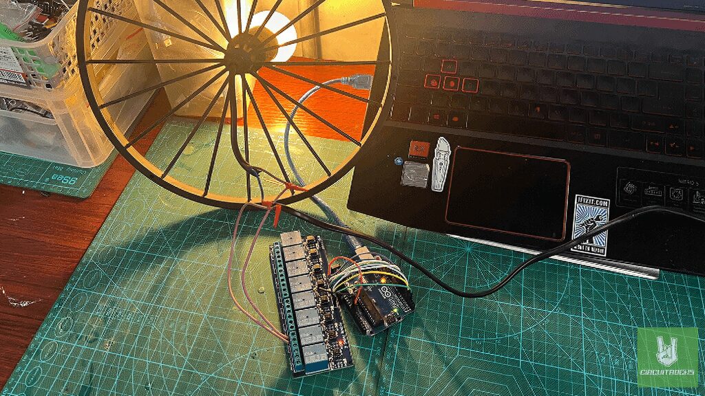
Learning how to test and control an 8-channel relay module using an Arduino is an important skill. Relays allow you to control high-power devices using low-power signals, which is essential in many complex projects. This tutorial will guide you through the basics of setting up and testing a relay channel with an Arduino. Giving you practical experience that helps you understand how relays work in a circuit.
You’ll start by setting up a simple system to control a single relay channel with an Arduino. The goal is to help you get comfortable with turning a relay on and off, which is a key step in understanding how these components function. However, since this tutorial involves an AC relay, it’s crucial to take precautions. Working with AC power can be dangerous, so make sure to handle all connections with care. Double-check your wiring and avoid touching any live circuits. It’s important to always unplug the power source before making any adjustments to ensure safety.
This hands-on practice is valuable because it connects what you’ve learned in theory to real-world applications. Gaining this foundational knowledge is crucial if you want to move on to more advanced projects that involve multiple relays or integrating relays into larger systems. Remember, safety is a priority, especially when working with high-voltage AC power. Taking the necessary precautions will help you safely and effectively complete this tutorial and any future projects.
Components
Connection:
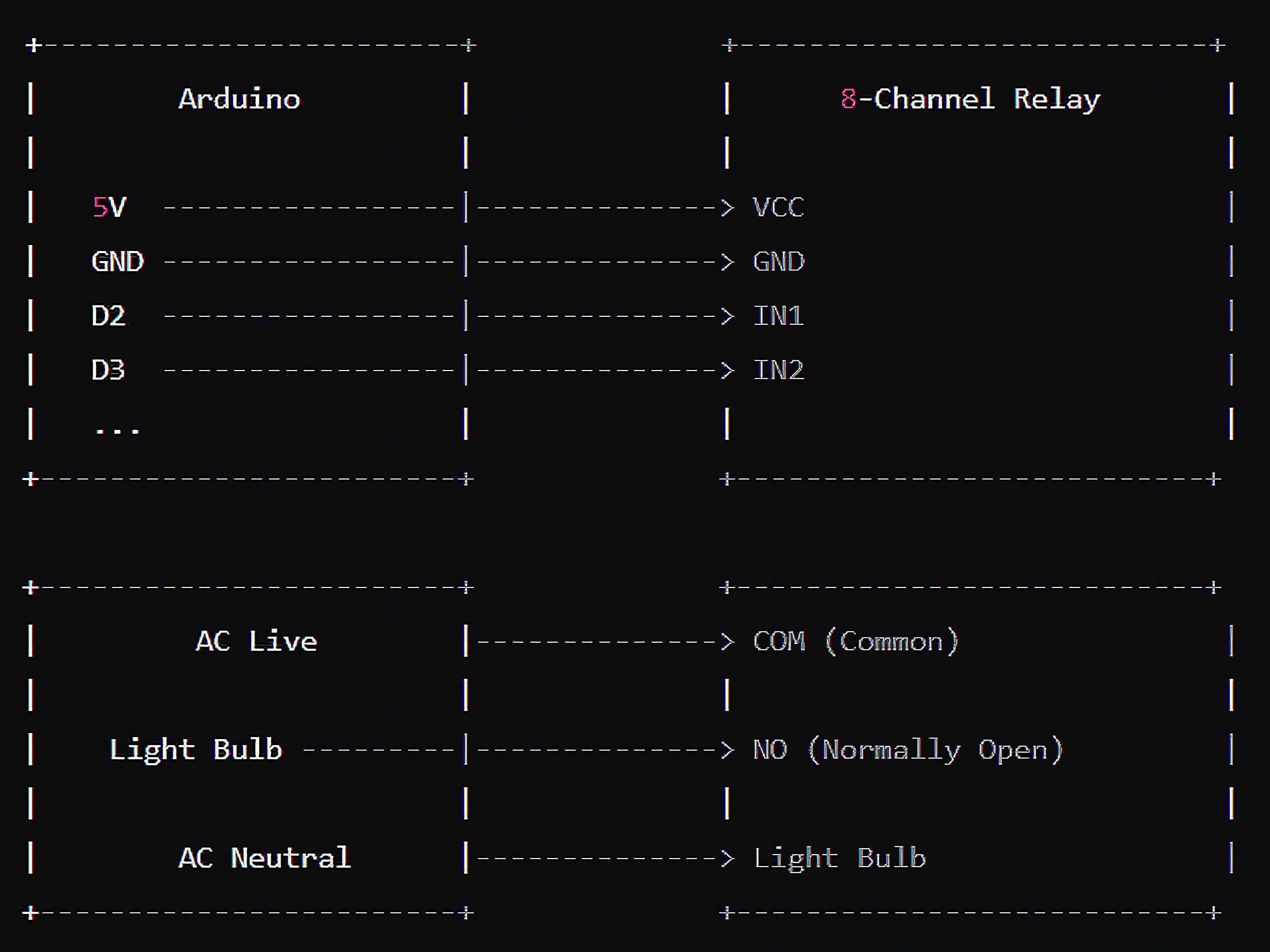
Power Connections:
- Relay Module VCC → Arduino 5V (or external 5V power supply if the relay module requires more current).
- Relay Module GND → Arduino GND.
Control Connections:
- IN1 → Arduino D2.
- IN2 → Arduino D3.
- IN3 → Arduino D4.
- IN4 → Arduino D5.
- IN5 → Arduino D6.
- IN6 → Arduino D7.
- IN7 → Arduino D8.
- IN8 → Arduino D9.
8 Channel Relay:
- Common (COM) Terminal of the Relay → AC Live Wire.
- Normally Open (NO) Terminal → AC Device (e.g., light bulb).
- Other Terminal of the AC Device → AC Neutral Wire
Code:
In the loop() function, the code toggles the state of the relay by changing the output of the relayPin. First, it writes LOW to the pin, which activates the relay, turning it on. This causes the connected device (e.g., a light bulb or motor) to be powered. The code then pauses for one second using delay(1000);, allowing you to observe the relay’s activation. After the delay, the code writes HIGH to the pin, deactivating the relay and turning it off. Another one-second delay follows, giving you time to see the relay switch off. This loop continues indefinitely, providing a simple way to observe the relay’s operation.
int relayPins[8] = {2, 3, 4, 5, 6, 7, 8, 9}; void setup() { // Initialize each relay pin as an output for (int i = 0; i < 8; i++) { pinMode(relayPins[i], OUTPUT); digitalWrite(relayPins[i], HIGH); // Set all relays to off }
} void loop() { // Turn each relay on and off with a delay for (int i = 0; i < 8; i++) { digitalWrite(relayPins[i], LOW); // Turn relay on delay(1000); // Wait 1 second digitalWrite(relayPins[i], HIGH); // Turn relay off delay(1000); // Wait 1 second }
}
Important Safety Tips:
- Unplug the Power: Before making or modifying any connections, ensure the power is unplugged to avoid the risk of electric shock.
- Double-Check Wiring: Make sure all connections are secure and correctly placed to prevent any short circuits.
- Handle AC Power with Caution: AC power can be dangerous. If you are not confident in your ability to work with it safely, seek help from someone experienced.
QUICK LINKS
Frequently Asked Questions
What does this 8-Channel Relay Testing via Arduino tutorial cover?
Learning how to test and control an 8-channel relay module using an Arduino is an important skill.
What Arduino library does the 8-Channel Relay Testing via Arduino tutorial use?
The sketch uses standard Wire.h (I2C) or SPI.h plus a part-specific library installable via Arduino IDE → Sketch → Include Library → Manage Libraries. See the Sample Code section.
Why does the 8-Channel Relay Testing via Arduino act differently on USB power vs battery?
Battery voltage sags under load. Add a 100uF cap across the rails, use a 5V/2A regulator-backed pack, and never power motors from the Arduino's onboard regulator.