
Building a traffic light circuit on a breadboard with basic components serves as an excellent project for electronics enthusiasts. This project introduces the fundamentals of electronic circuit. The use of timer circuits to manage the timing and sequencing of LED. It teaches the role of resistors and capacitors in regulating current flow and voltage across a circuit. It simulates the operation of actual traffic signals, providing practical experience.
The first 555 timer in astable mode, which incessantly oscillates between high and low state. Generating a clock pulse that drives the rotational cycle of the traffic lights. The timing of this cycle regulated by altering the values of the resistors and capacitors connected to the timer.
The second 555 timer operates in monostable mode to create specific timing intervals for each light. The monostable timer triggered outputs high signal for a duration determined by the resistor and capacitor. For controlling the LEDs, each LED is connected through a current-limiting resistor to one of the outputs of the 555 timers. The resistors ensure that the correct amount of current flows through each LED, protecting them from excessive current that could lead to damage.
Going on this project is very beneficial for newcomers. They can build traffic light circuits which in turn deepens their understanding and moves them forward for other advanced projects.
Components
Connection:
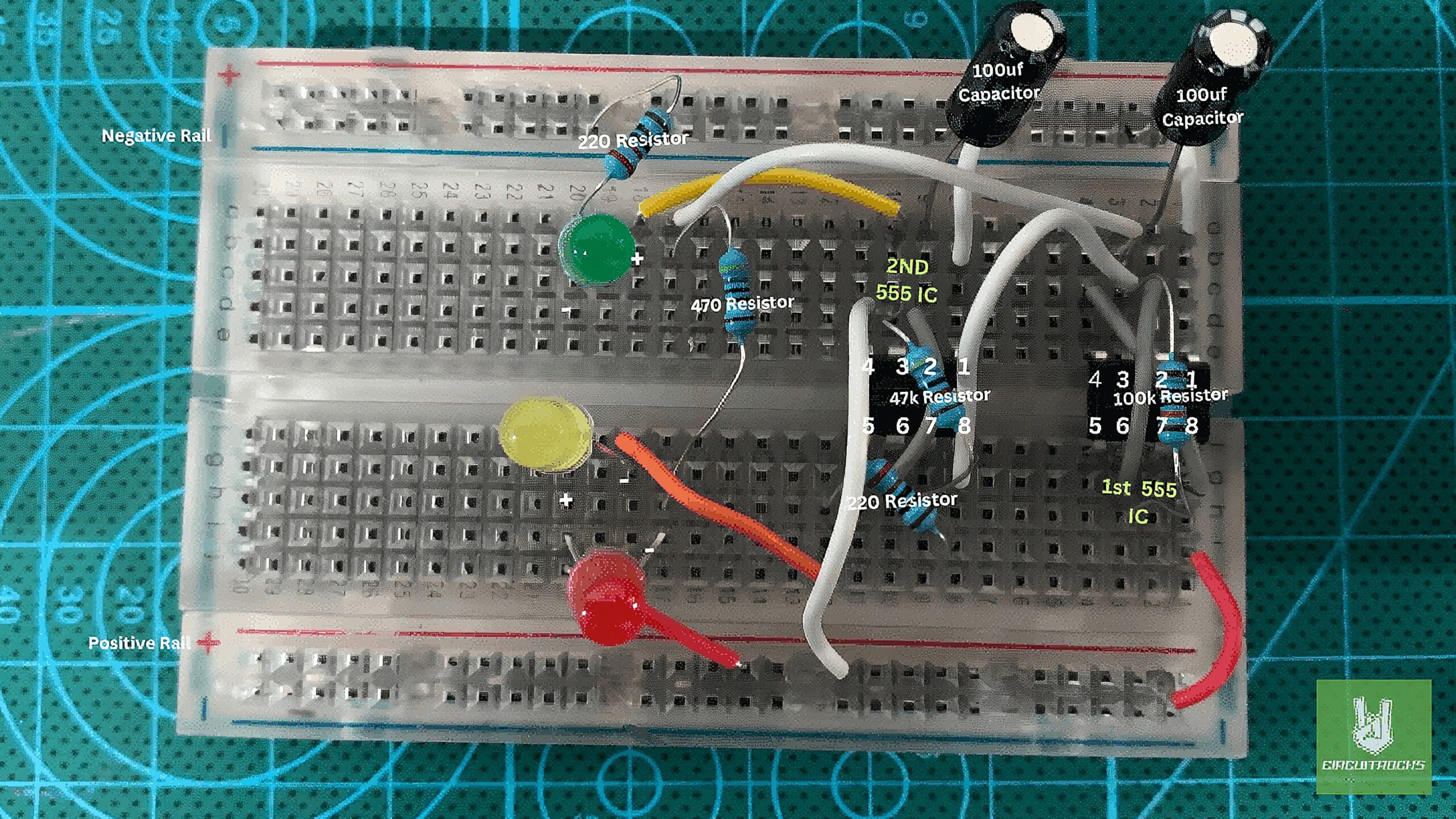
First 555 IC Setup:
- Connect Pin 1 to the breadboard’s negative rail using a white wire.
- Connect Pin 8 to the positive rail using a red wire.
- Bridge Pins 4 and 8 with a medium gray wire.
- Link Pins 2 and 6 together using another medium gray wire.
- Attach a 100k resistor between Pin 3 and Pin 6.
- Connect a 100uF capacitor from Pin 2 to the negative rail.
Second 555 IC Setup:
- Connect Pin 8 of the second 555 IC to Pin 3 of the first 555 IC using a large white wire.
- Use another white wire to link Pin 1 to the negative rail.
- Use a medium gray wire to connect Pins 2 and 6.
- Attach a 47k resistor between Pin 3 and Pin 6.
- Connect Pin 4 to the positive rail using a large white wire.
- Place a 100uF capacitor from Pin 2 to the negative rail.
Connecting the LEDs:
- Red LED: Attach the anode to the positive rail and connect the cathode to Pin 3 of the first 555 IC via a 470 ohm resistor.
- Yellow LED: Link the anode with the red LED’s anode and connect the cathode to Pin 7 of the second 555 IC through a 220 ohm resistor.
- Green LED: Connect the anode directly to Pin 3 of the second 555 IC using a medium yellow wire with a 220 ohm resistor.
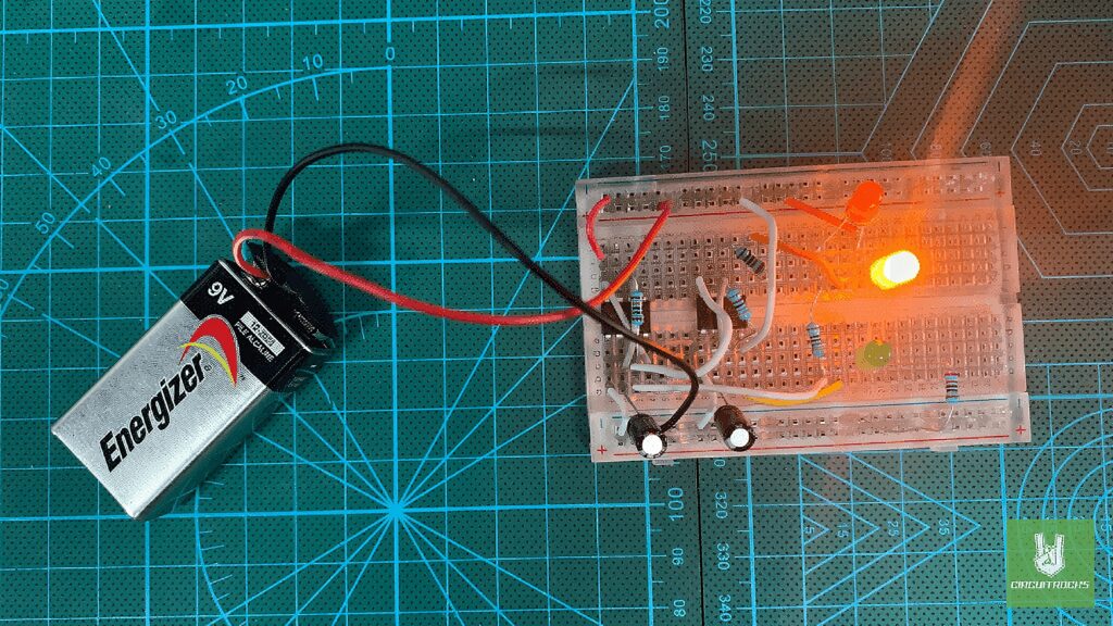
Connect the Battery:
- Attach the positive terminal of your battery to the positive rail of the breadboard.
- Connect the negative terminal to the negative rail. This setup will power the entire circuit.
This setup allows you to simulate a traffic light, with each 555 timer controlling the timing for different lights. Adjust the resistor and capacitor values to change the timing as needed.
QUICK LINK
Frequently Asked Questions
What does this Traffic Light Circuit tutorial cover?
Building a traffic light circuit on a breadboard with basic components serves as an excellent project for electronics enthusiasts.
What's the working voltage of the Traffic Light Circuit?
Check the Sample Code section for the exact pinout — most maker-grade sensors run on 3.3V or 5V. Wire VCC to the matching rail, GND common with your MCU, data to a digital or analog pin.
Why does the Traffic Light Circuit read garbage or saturated values?
Three usual causes: wrong voltage rail, missing pull-up resistor on I2C lines (4.7k–10k to VCC), or a floating data pin. Double-check wiring against the diagram, then probe with a multimeter.