
The Airplane Light Blinker Circuit involves designing a circuit. It uses basic components like IC NE555, 9v battery, capacitor, resistor and a 5 LED. Eliminating the need for a microcontroller like Arduino. Two LED on the left wing, two LED for the right wing, and one LED on the nose of an airplane. Using IC NE555 to blink in a specific manner like aircraft’s navigation lights.
The purpose of this project is to replicate the lighting found on real aircraft. Which helps in identifying the aircraft’s position. This project uses yellow LEDs for simplicity. The LEDs on the wings and nose will blink in a specific pattern to mimic real-world navigation lights. This setup demonstrates the importance of navigation lights.
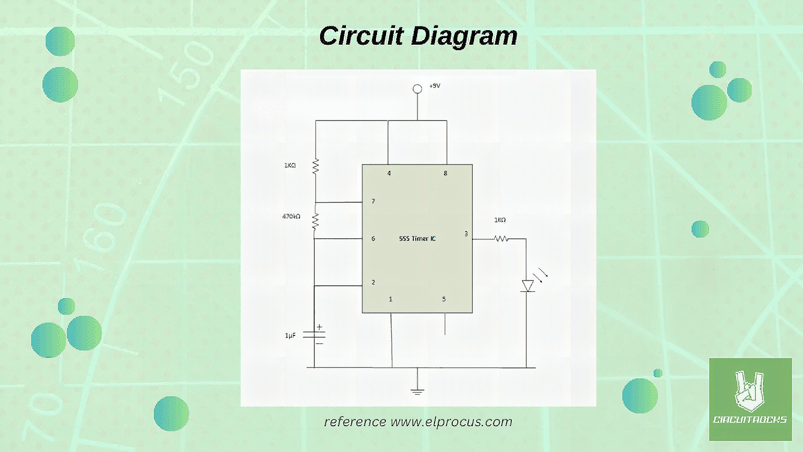
To execute this, we will use a 555 timer IC configured in astable mode state. It generates a continuous signal, which will control the blinking of LED. The circuit will be powered by a 9V battery, and resistors will be used to limit the current, preventing damage of LED. A 2.2µF µF capacitor, placed in the timing circuit sets the blink rate of the LED to blink its unison. This simple setup provides a practical experience in electronics. Demonstrating how to create an Airplane Light Blinker Circuit using basic components of it.
Components
Connection:
Notes:
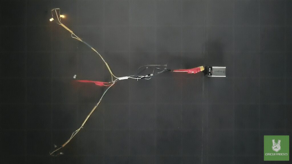
To effectively use a soldering iron, solder lead, solder flux, and heat shrink, follow this simple guide.
- Plug in and heat the soldering iron until it reaches the desired temperature. Apply a small amount of solder to the iron’s tip to “tin” it, ensuring better heat conductivity.
- Next, apply solder flux to the components or wires you intend to join. This helps the solder flow smoothly and creates a strong bond. Hold the soldering iron against the joint area to heat it.
- Then touch the solder lead to the heated joint (not the iron) to melt the solder, allowing it to flow and cover the connection.
- Remove the soldering iron and let the joint cool naturally without moving it to ensure a solid connection.
- Once the solder has cooled, slide the heat shrink tubing over the joint, and use a heat gun or the side of the soldering iron to shrink the tubing, providing insulation and protecting the connection.
QUICK LINK
Frequently Asked Questions
What does this Airplane Light Blinker Circuit tutorial cover?
The Airplane Light Blinker Circuit involves designing a circuit.
What Arduino library does the Airplane Light Blinker Circuit tutorial use?
The sketch uses standard Wire.h (I2C) or SPI.h plus a part-specific library installable via Arduino IDE → Sketch → Include Library → Manage Libraries. See the Sample Code section.
Why does the Airplane Light Blinker Circuit act differently on USB power vs battery?
Battery voltage sags under load. Add a 100uF cap across the rails, use a 5V/2A regulator-backed pack, and never power motors from the Arduino's onboard regulator.