
Wiring
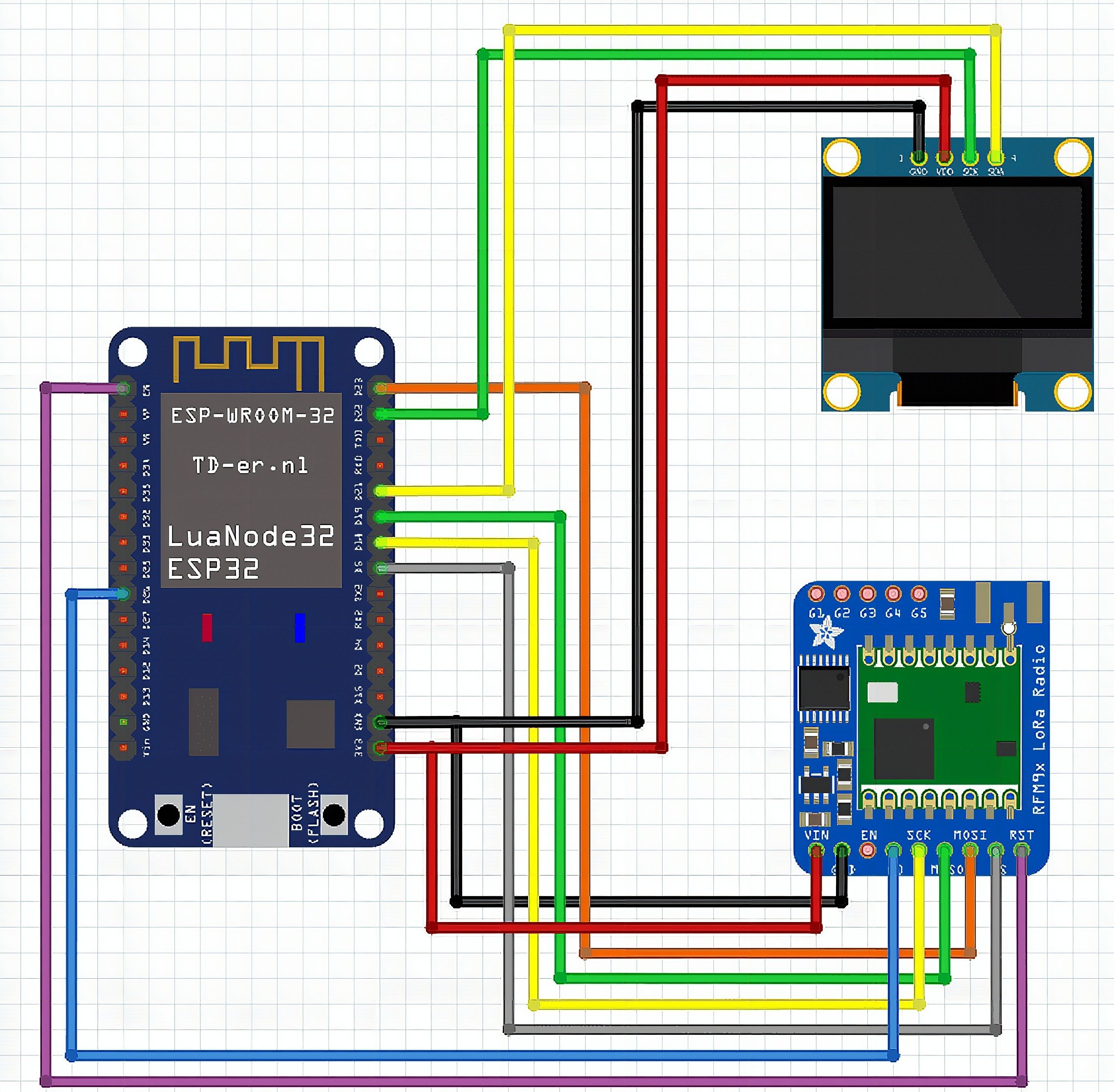
The gateway connections
- The LoRa module connections:
- The power pins (VIN and GND) are connected to the ESP32s power pins. The RFM95 modules work well with both 3.3V and 5V.
- The SPI pins SCK, MISO, MOSI and CS of the LoRa module are connected to the default VSPI pins of the ESP32, GPIOs 18, 19, 23 and 5.
- The DIO0 pin (G0 in the Fritzing diagram) is the interrupt signal of the LoRa module. You can connect it to any GPIO of the ESP32 that works as an input, I chose GPIO 26.
- The RST pin could be connected to an GPIO as well to be able to manually reset the LoRa module. But on the module I used (see the very first picture), there was no access to this pin, because the LoRa module was integrated on the ESP32 board. So here it is only connected to the EN pin of the ESP32, which is the ESP32s reset pin.
- The display connections:
- The I2C pins from the display are connected to the default I2C pins of the ESP32 (GPIO21 = SCL, GPIO22 = SDA).
- The power pins from the display are connected to 3.3V and GND of the ESP32.
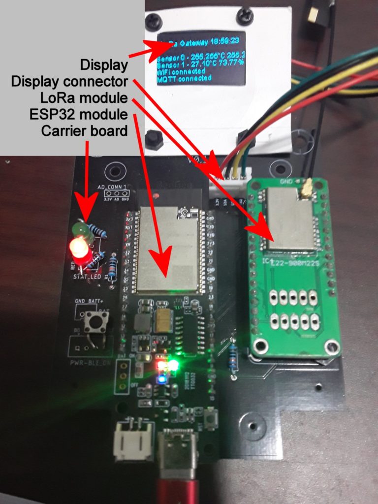
The layout of the carrier PCB is quite simple and it looks much better than the hand-wired sensor nodes.
If you want to make your own PCB’s, it is not that expensive. Just get an account on SEEED and order 10 PCB’s with a max size of 100x100mm for around 25US$ (including shipping cost).
Required libraries
The gateway needs three additional libraries. 2 libraries are available through the library manager of ArduinoIDE. The 3th library needs to be installed manually.
RadioLib
Different to the first tutorial I switched to the RadioLib library. There are 2 reasons for the switch.
1) RadioLib supports both LoRa chips that I used, the SX127x and the SX126x. The RadioHead library used before doesn’t support the SX126x chips.
2) RadioLib has an important function called CAD (channel activity detection). We will need this function to make sure that we do not send LoRa packages from two nodes at the same time. Sending on the same frequency from two nodes at the same time would result in a destroyed package.
Adafruit MQTT
This library is only needed for the gateway. It handles the communication with the Adafruit IoT service
ESP8266 and ESP32 Oled Driver for SSD1306
This is the only library that I didn’t find in ArduinoIDE. So you have to download the library from Github and install it manually. So you have to download it from here (look for the  button). Save it on your harddisk and add it to ArduinoIDE by using Sketch->Include library->Add.ZIP library button).
The LoRa gateway software
Some snippets from the code that will help to understand the code better.
Define the data packages
To make sure the LoRa gateway knows
a) that the received data package is from a sensor it is supposed to listen to and not from another persons LoRa node
b) which sensor sent the data
To achieve this, I defined a structure for the data package which looks like this:
1 byte sensor ID – 0 to 255 for 256 possible sensor nodes
1 byte magic byte – always 0xAA
4 bytes for the data – can be any kind of sensor data
So the gateways has 2 identifiers to know that the package is from a known sensor node.
a) The data package is 6 bytes long
b) The data package contains the magic byte (which is 0xAA)
This is not bullet-proof, it still can happen that a package from a foreign LoRa node has 6 bytes length and the second byte is 0xAA. But it should be enough for this tutorial. To make it more secure, you can extend the package size and for example put more magic bytes into the structure, e.g. one magic byte between each of the sensor data bytes.
Using the display
The display is quite easy to use. The library creates an internal buffer to hold whatever should be shown on the display. This buffer is sent to the display with the display.display() function. In addition the software defines a buffer of 6 Strings that are used to store the text for each line of the display. This way, I can change a single line and then just call my function updateDisplay() which then just writes all 6 Strings to the display buffer and calls the display.display() function to update the display.
// Display class
// I2C addr, SDA pin, SCL pin
SH1106Wire display(0x3c, 21, 22); // Display buffer
String lines[6]; void setup()
{ // Initialize the display display.init(); display.displayOn(); display.flipScreenVertically(); display.setContrast(255); display.setFont(ArialMT_Plain_10); // Update the text for the top line lines[0] = "LoRa Gateway"; // update the display updateDisplay();
}
The updateDisplay() function is writing the content of the 6 line strings into the library buffer and then calls display.display() to update the display content.
void updateDisplay(void)
{ display.clear(); display.setTextAlignment(TEXT_ALIGN_LEFT); for (uint8_t idx = 0; idx < 6; idx++) { if (idx == 0) { int strWidth = display.getStringWidth(lines[0]); display.drawString(64 - (strWidth / 2), 0, lines[0]); } else { // display.drawString(0, ((idx + 1) * 10) + 1, lines[idx]); display.drawString(0, ((idx) * 10) + 1, lines[idx]); } } display.display();
}
Choose the SPI peripheral
The ESP32 has two SPI interfaces, called VSPI and HSPI. They have different default GPIOs. Depending to which SPI you have connected the LoRa module, the initialization of the RadioLib class looks different
// Using VSPI and a SX1262 module
SPIClass *loraSPI = new SPIClass(VSPI);
// NSS DIO1 DIO2 BUSY
SX1262 lora = new Module(5, 26, -1, 25, *loraSPI); // Using HSPI and a SX1276 (RFM95W) module
SPIClass *loraSPI = new SPIClass(HSPI);
// NSS DIO0 DIO1
SX1276 lora = new Module(16, 26, 33, *loraSPI);
As you can see, to specify the SPI bus used, we define a pointer to the SPI class giving a parameter that defines to use HSPI or VSPI. Then when initializing the RadioLib class, we give the SPI pointer as a parameter.
The other parameters set the other control lines between the ESP32 and the LoRa module. They are different for the SX1276 and the SX1262.
Initializing the LoRa module
The initialization using the RadioLib class is different to what we saw in RadioHead library. Here we give 4 parameters (out of many more, check the library to see the options) to start all LoRa modules with the same settings. Here we chose 868.0MHz as base frequency, a bandwidth of 125kHz, a spreading factor of 8 and a coding rate of 4/5. What does all of this mean? I don’t want to go into these details here, because I want to concentrate on the principal usage of LoRa. But as mentioned in my other blog, check out the technical paper of the LoRa Alliance.
// Initialize LoRa int state = lora.begin(868.0, 125.0, 8, 5);Receiving data packages from the sensor nodes
Receiving data from the sensor nodes is simple. In the main loop we just call lora.receive(). This function is listening for data packets transmitted over LoRa. If it receives a package, it returns the value ERR_NONE, then we process the received package data. If no package was received for some time, lora.receive() will return ERR_RX_TIMEOUT, which will happen most of the time. Then we just restart to listen for incoming LoRa packets.
// Check if data over LoRa is available int state = lora.receive(dataMsg, sizeof(dataMsg)); switch (state) { case ERR_NONE: Serial.println("---"); digitalWrite(LED_BUILTIN, LOW); //Turn on status LED timeSinceLastPacket = millis(); //Timestamp this packet Serial.printf("Got data package: 0x%02X-0x%02X-0x%02X-0x%02X-0x%02X-0x%02X RSSI: %.2fn", dataMsg[0], dataMsg[1], dataMsg[2], dataMsg[3], dataMsg[4], dataMsg[5], lora.getRSSI()); nodeId = (uint16_t)(dataMsg[0]) << 8; nodeId = nodeId | dataMsg[1]; Serial.printf("Node ID: %04Xn", nodeId); float valueAsFloat; // Handle the different sensor packages switch (nodeId) { case 0x00AA: // Sensor 0 and magic byte 0xAA getLocalTime(&timeinfo); sprintf(timeStamp, "%04d-%02d-%02d %02d:%02d:%02d", timeinfo.tm_year + 1900, timeinfo.tm_mon + 1, timeinfo.tm_mday, timeinfo.tm_hour, timeinfo.tm_min, timeinfo.tm_sec); // Temperature sensor tempInt = dataMsg[2]; tempFrac = dataMsg[3]; humidInt = dataMsg[4]; humidFrac = dataMsg[5]; Serial.printf("Got data from sensor 0 - temperature %d.%2dC humidity %d.%2d%% at %sn", tempInt, tempFrac, humidInt, humidFrac, timeStamp); valueAsFloat = ((float)tempFrac / 100.0) + (float)tempInt; if (!temp_feed.publish(valueAsFloat)) { Serial.println("Publishing temperature failed"); } valueAsFloat = ((float)humidFrac / 100.0) + (float)humidInt; if (!humid_feed.publish(valueAsFloat)) { Serial.println("Publishing humiditiy failed"); } lines[2] = "Sensor 0 - " + String(tempInt) + "." + String(tempFrac) + "`C " + String(humidInt) + "." + String(humidFrac) + "%"; updateDisplay(); break; case 0x01AA: // Sensor 1 and magic byte 0xAA // Environment sensor getLocalTime(&timeinfo); sprintf(timeStamp, "%04d-%02d-%02d %02d:%02d:%02d", timeinfo.tm_year + 1900, timeinfo.tm_mon + 1, timeinfo.tm_mday, timeinfo.tm_hour, timeinfo.tm_min, timeinfo.tm_sec); // Temperature sensor tempInt = dataMsg[2]; tempFrac = dataMsg[3]; humidInt = dataMsg[4]; humidFrac = dataMsg[5]; Serial.printf("Got data from sensor 1 - temperature %d.%2dC humidity %d.%2d%% at %sn", tempInt, tempFrac, humidInt, humidFrac, timeStamp); valueAsFloat = ((float)tempFrac / 100.0) + (float)tempInt; if (!temp1_feed.publish(valueAsFloat)) { Serial.println("Publishing temperature failed"); } valueAsFloat = ((float)humidFrac / 100.0) + (float)humidInt; if (!humid1_feed.publish(valueAsFloat)) { Serial.println("Publishing humiditiy failed"); } lines[3] = "Sensor 1 - " + String(tempInt) + "." + String(tempFrac) + "`C " + String(humidInt) + "." + String(humidFrac) + "%"; updateDisplay(); break; default: Serial.println("Unknown sensor ID, dismiss the package"); break; } break; case ERR_RX_TIMEOUT: // Serial.println("Receive timeout"); break; case ERR_CRC_MISMATCH: Serial.println("CRC mismatch"); break; default: Serial.printf("Unknown error %dn", state); break; }
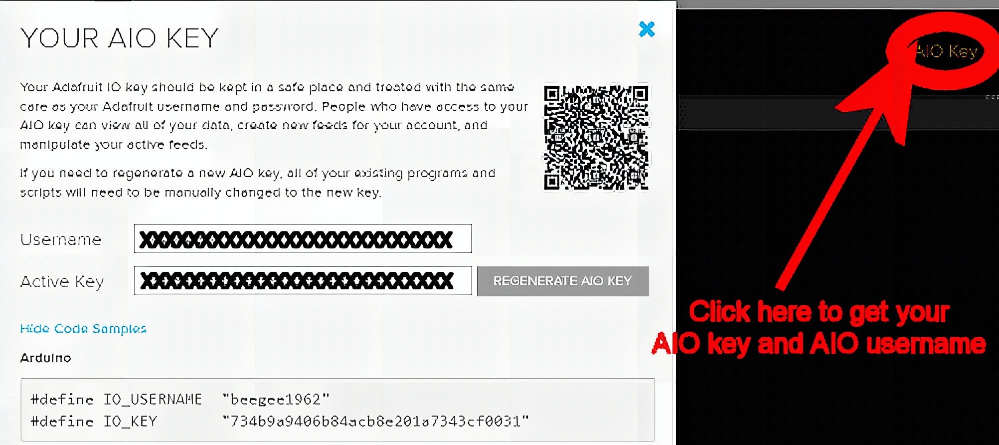
Initialize the connection to the cloud = io.adafruit.com
To be able to send data to the io.adafruit IoT cloud service you will have to sign up for an Adafruit IO account. What we need here in the software are
the AIO_USERNAME and AIO_KEY to be able to send data to io.adafruit.com.
While logged into your Adafruit IO account click on the AIO Key button to get these two values.
I don’t want to go into details how to setup feeds and dashboards here, JP Tan explained the steps in his tutorial and you can find many more on examples on Adafruit Learn.
In the code I use the feed names t_node_0 & h_node_0 for data from sensor 0 and t_node_1 & h_node_1 for data from sensor 1. But you can use any feed name you want.
Once you have your username and key, you can setup the code
// Adafruit IoT stuff
// Username
#define AIO_USERNAME "XXXXXXXX"
// Active key
#define AIO_KEY "XXXXXXXXXXXXXXXXXXXXXXXXXXXXXXXXX"
// Server URL
#define AIO_SERVER "io.adafruit.com"
// Server port
#define AIO_SERVERPORT 1883 // use 8883 for SSL WiFiClient client;
Adafruit_MQTT_Client mqtt(&client, AIO_SERVER, AIO_SERVERPORT, AIO_USERNAME, AIO_KEY); // Feed for temperature of sensor 0
Adafruit_MQTT_Publish temp_feed = Adafruit_MQTT_Publish(&mqtt, AIO_USERNAME "/feeds/t_node_0");
// Feed for humidity of sensor 0
Adafruit_MQTT_Publish humid_feed = Adafruit_MQTT_Publish(&mqtt, AIO_USERNAME "/feeds/h_node_0");
// Feed for temperature of sensor 1
Adafruit_MQTT_Publish temp1_feed = Adafruit_MQTT_Publish(&mqtt, AIO_USERNAME "/feeds/t_node_1");
// Feed for humidity of sensor 1
Adafruit_MQTT_Publish humid1_feed = Adafruit_MQTT_Publish(&mqtt, AIO_USERNAME "/feeds/h_node_1");
To connect to io.adafruit we use the function MQTT_connect() that does 2 things:
It checks if we have a connection to io.adafruit.com. If not it tries to connect to the IoT cloud service.
If there is no WiFi connection, it tries first to reconnect to the WiFi. This functions is called frequently from the main loop to make sure that we have a connection to the IoT cloud service.
void MQTT_connect()
{ int8_t ret; // Stop if already connected. if (mqtt.connected()) { return; } if (WiFi.isConnected()) { lines[4] = "WiFi connected"; lines[5] = "MQTT connecting"; updateDisplay(); Serial.print("Connecting to MQTT... "); uint8_t retries = 3; while ((ret = mqtt.connect())!= 0) { // connect will return 0 for connected Serial.println(mqtt.connectErrorString(ret)); Serial.println("Retrying MQTT connection in 5 seconds..."); mqtt.disconnect(); delay(5000); // wait 5 seconds retries--; if (retries == 0) { lines[5] = "MQTT error"; updateDisplay(); } } if (mqtt.connected()) { Serial.println("MQTT Connected!"); lines[5] = "MQTT connected"; updateDisplay(); } } else { lines[4] = "WiFi disconnected"; updateDisplay(); WiFi.reconnect(); }
}
Sending a data set to the IoT cloud is very simple by using the “feeds” we defined before, e.g. Adafruit_MQTT_Publish temp_feed = Adafruit_MQTT_Publish(&mqtt, AIO_USERNAME “/feeds/t_node_0”);
The send the data its a simple call of temp_feed.publish().
The rest of the code is “standard”, initialize the Serial connection, connect to a WiFi network,… I leave it to you to go through the source code.
#include <Arduino.h>
#include <WiFi.h>
#include <RadioLib.h> #include <Adafruit_MQTT.h>
#include <Adafruit_MQTT_Client.h> #include <SH1106Wire.h> // Display class
// I2C addr, SDA pin, SCL pin
SH1106Wire display(0x3c, 21, 22); // Display buffer
String lines[6]; // Timer for display updates
time_t updateTime; // Flag for sending finished
bool sendDone = false; // Function declarations
void updateDisplay(void);
void MQTT_connect();
void rxEnable(void);
void txEnable(void); // SPI class used by RadioLib
SPIClass *loraSPI = new SPIClass(VSPI);
// NSS DIO1 DIO2 BUSY
SX1262 lora = new Module(5, 21, -1, 22, *loraSPI); // LORA ANTENNA TX ENABLE
int RADIO_TXEN = 26;
// LORA ANTENNA RX ENABLE
int RADIO_RXEN = 27;
// LORA Reset pin
int PIN_LORA_RESET = 4; // Define a LED port if not already defined
//#ifndef LED_BUILTIN
// Change this to the GPIO connected to an LED
#define LED_BUILTIN 15
//#endif // Adafruit IoT stuff
// Username
#define AIO_USERNAME "<PUT_YOUR_AIO_USERNAME_HERE>"
// Active key
#define AIO_KEY "<PUT_YOUR_AIO_KEY_HERE>"
// Server URL
#define AIO_SERVER "io.adafruit.com"
// Server port
#define AIO_SERVERPORT 1883 // use 8883 for SSL // PUT YOUR OWN WIFI AP NAME AND PASSWORD HERE
// WiFi AP name
#define ssid "MyWiFi"
// WiFi password
#define pass "qwerty123" // WiFi client to connect to IoT service
WiFiClient client;
// MQTT client to connect to io.adafruit.com
Adafruit_MQTT_Client mqtt(&client, AIO_SERVER, AIO_SERVERPORT, AIO_USERNAME, AIO_KEY); // Feed for temperature of sensor 0
Adafruit_MQTT_Publish temp_feed = Adafruit_MQTT_Publish(&mqtt, AIO_USERNAME "/feeds/t_node_0");
// Feed for humidity of sensor 0
Adafruit_MQTT_Publish humid_feed = Adafruit_MQTT_Publish(&mqtt, AIO_USERNAME "/feeds/h_node_0");
// Feed for temperature of sensor 1
Adafruit_MQTT_Publish temp1_feed = Adafruit_MQTT_Publish(&mqtt, AIO_USERNAME "/feeds/t_node_1");
// Feed for humidity of sensor 1
Adafruit_MQTT_Publish humid1_feed = Adafruit_MQTT_Publish(&mqtt, AIO_USERNAME "/feeds/h_node_1");
// Structure for current time info
struct tm timeinfo;
// Char array for display time // The Ping message will be sent by the node
uint8_t dataMsg[6];
// The Pong message will be sent by the gateway
char ackMsg[] = "ACK";
// Tracks the time stamp of last packet received
long timeSinceLastPacket = 0; // Id of the node that sent a package
uint16_t nodeId = 0; // Temperature integer part
uint8_t tempInt;
// Temperature fraction part
uint8_t tempFrac;
// Humidity integer part
uint8_t humidInt;
// Humidity fraction part
uint8_t humidFrac; // Array to write date/time as string
char timeStamp[32]; void setup()
{ pinMode(PIN_LORA_RESET, OUTPUT); digitalWrite(PIN_LORA_RESET, HIGH); // Start serial communication Serial.begin(115200); // Initialize LoRa int state = lora.begin(868.0, 125.0, 8, 5); if (state!= ERR_NONE) { Serial.printf("nLoRa begin failed %dnn", state); } lora.setOutputPower(22); lora.setTCXO(2.4); lora.setDio2AsRfSwitch(true); pinMode(LED_BUILTIN, OUTPUT); pinMode(RADIO_TXEN, OUTPUT); pinMode(RADIO_RXEN, OUTPUT); rxEnable(); Serial.println("====================================="); Serial.println("LoRa gateway test"); Serial.println("====================================="); // Initialize the display display.init(); display.displayOn(); display.flipScreenVertically(); display.setContrast(255); display.setFont(ArialMT_Plain_10); // Update the text for the top line lines[0] = "LoRa Gateway"; // Initialize WiFi connection WiFi.begin(ssid, pass); lines[4] = "WiFI connecting"; updateDisplay(); while (WiFi.status()!= WL_CONNECTED) { delay(500); Serial.print("."); } lines[4] = "WiFI connected"; updateDisplay(); // Initialize time configTzTime("UTC-8:00", "0.asia.pool.ntp.org", "1.asia.pool.ntp.org", "2.asia.pool.ntp.org"); getLocalTime(&timeinfo); rxEnable();
} void loop()
{ // Check if we are connected to IO.Adafruit.com MQTT_connect(); uint8_t retryCAD = 0;
// rxEnable(); // Check if data over LoRa is available int state = lora.receive(dataMsg, sizeof(dataMsg)); switch (state) { case ERR_NONE: Serial.println("---"); digitalWrite(LED_BUILTIN, LOW); //Turn on status LED timeSinceLastPacket = millis(); //Timestamp this packet Serial.printf("Got data package: 0x%02X-0x%02X-0x%02X-0x%02X-0x%02X-0x%02X RSSI: %.2fn", dataMsg[0], dataMsg[1], dataMsg[2], dataMsg[3], dataMsg[4], dataMsg[5], lora.getRSSI()); nodeId = (uint16_t)(dataMsg[0]) << 8; nodeId = nodeId | dataMsg[1]; Serial.printf("Node ID: %04Xn", nodeId); float valueAsFloat; // Handle the different sensor packages switch (nodeId) { case 0x00AA: // Sensor 0 and magic byte 0xAA getLocalTime(&timeinfo); sprintf(timeStamp, "%04d-%02d-%02d %02d:%02d:%02d", timeinfo.tm_year + 1900, timeinfo.tm_mon + 1, timeinfo.tm_mday, timeinfo.tm_hour, timeinfo.tm_min, timeinfo.tm_sec); // Temperature sensor tempInt = dataMsg[2]; tempFrac = dataMsg[3]; humidInt = dataMsg[4]; humidFrac = dataMsg[5]; Serial.printf("Got data from sensor 0 - temperature %d.%2dC humidity %d.%2d%% at %sn", tempInt, tempFrac, humidInt, humidFrac, timeStamp); valueAsFloat = ((float)tempFrac / 100.0) + (float)tempInt; if (!temp_feed.publish(valueAsFloat)) { Serial.println("Publishing temperature failed"); } valueAsFloat = ((float)humidFrac / 100.0) + (float)humidInt; if (!humid_feed.publish(valueAsFloat)) { Serial.println("Publishing humiditiy failed"); } lines[2] = "Sensor 0 - " + String(tempInt) + "." + String(tempFrac) + "`C " + String(humidInt) + "." + String(humidFrac) + "%"; updateDisplay(); break; case 0x01AA: // Sensor 1 and magic byte 0xAA // Environment sensor getLocalTime(&timeinfo); sprintf(timeStamp, "%04d-%02d-%02d %02d:%02d:%02d", timeinfo.tm_year + 1900, timeinfo.tm_mon + 1, timeinfo.tm_mday, timeinfo.tm_hour, timeinfo.tm_min, timeinfo.tm_sec); // Temperature sensor tempInt = dataMsg[2]; tempFrac = dataMsg[3]; humidInt = dataMsg[4]; humidFrac = dataMsg[5]; Serial.printf("Got data from sensor 1 - temperature %d.%2dC humidity %d.%2d%% at %sn", tempInt, tempFrac, humidInt, humidFrac, timeStamp); valueAsFloat = ((float)tempFrac / 100.0) + (float)tempInt; if (!temp1_feed.publish(valueAsFloat)) { Serial.println("Publishing temperature failed"); } valueAsFloat = ((float)humidFrac / 100.0) + (float)humidInt; if (!humid1_feed.publish(valueAsFloat)) { Serial.println("Publishing humiditiy failed"); } lines[3] = "Sensor 1 - " + String(tempInt) + "." + String(tempFrac) + "`C " + String(humidInt) + "." + String(humidFrac) + "%"; updateDisplay(); break; default: Serial.println("Unknown sensor ID, dismiss the package"); break; }
// rxEnable(); break; case ERR_RX_TIMEOUT: // Serial.println("Receive timeout"); break; case ERR_CRC_MISMATCH: Serial.println("CRC mismatch"); break; default: Serial.printf("Unknown error %dn", state); break; } //Turn off status LED if we haven't received a packet after 30s if (millis() - timeSinceLastPacket > 30000) { digitalWrite(LED_BUILTIN, HIGH); //Turn off status LED timeSinceLastPacket = millis(); //Don't write LED but every 1s } // Update the display if ((millis() - updateTime) > 1000) { getLocalTime(&timeinfo, 100); sprintf(timeStamp, "LoRa Gateway %02d:%02d:%02d", timeinfo.tm_hour, timeinfo.tm_min, timeinfo.tm_sec); lines[0] = String(timeStamp); updateDisplay(); updateTime = millis(); }
} // Check io.adafruit / MQTT and WiFi connection
void MQTT_connect()
{ int8_t ret; // Stop if already connected. if (mqtt.connected()) { return; } if (WiFi.isConnected()) { lines[4] = "WiFi connected"; lines[5] = "MQTT connecting"; updateDisplay(); Serial.print("Connecting to MQTT... "); uint8_t retries = 3; while ((ret = mqtt.connect())!= 0) { // connect will return 0 for connected Serial.println(mqtt.connectErrorString(ret)); Serial.println("Retrying MQTT connection in 5 seconds..."); mqtt.disconnect(); delay(5000); // wait 5 seconds retries--; if (retries == 0) { lines[5] = "MQTT error"; updateDisplay(); } } if (mqtt.connected()) { Serial.println("MQTT Connected!"); lines[5] = "MQTT connected"; updateDisplay(); } } else { lines[4] = "WiFi disconnected"; updateDisplay(); WiFi.reconnect(); }
} // Update the display
void updateDisplay(void)
{ display.clear(); display.setTextAlignment(TEXT_ALIGN_LEFT); for (uint8_t idx = 0; idx < 6; idx++) { if (idx == 0) { int strWidth = display.getStringWidth(lines[0]); display.drawString(64 - (strWidth / 2), 0, lines[0]); } else { // display.drawString(0, ((idx + 1) * 10) + 1, lines[idx]); display.drawString(0, ((idx) * 10) + 1, lines[idx]); } } display.display();
}
Frequently Asked Questions
[faq] [faq_q]What is the difference between a LoRa gateway and a LoRa node?[/faq_q] [faq_a]A LoRa node sends sensor data over LoRa radio. A LoRa gateway listens for those transmissions and forwards them somewhere, usually over Wi-Fi or Ethernet to a server. Gateways have more compute and a network connection, nodes are minimal.[/faq_a] [faq_q]Do I need The Things Network for a LoRa gateway?[/faq_q] [faq_a]No. The Things Network is one option for a public LoRaWAN backend, but you can build a private gateway that talks directly to your own server. The article uses ESP32 and a custom backend, no TTN required.[/faq_a][faq_q]How many LoRa nodes can one gateway support?[/faq_q] [faq_a]Theoretically thousands, in practice 50-200 depending on transmission frequency and air time. LoRaWAN duty cycle limits how often each node can talk, which spreads out the load.[/faq_a][faq_q]Does the gateway need to be on a high vantage point?[/faq_q] [faq_a]Yes if you want long range. Gateway height matters more than node height for range. A rooftop gateway easily covers a few square kilometers in suburban areas.[/faq_a][faq_q]What is the difference between a single-channel and 8-channel LoRa gateway?[/faq_q] [faq_a]A single-channel gateway listens on one frequency at a time. An 8-channel gateway listens on 8 frequencies simultaneously, which is the LoRaWAN standard. Single-channel works for hobby projects, 8-channel for real LoRaWAN.[/faq_a][/faq]Frequently Asked Questions
What does this LoRa Gateway tutorial cover?
Part #2 – The LoRa gateway In my other post I made an introduction to Long Range (LoRa) communication .
What's the working voltage of the LoRa Gateway?
Check the Sample Code section for the exact pinout — most maker-grade sensors run on 3.3V or 5V. Wire VCC to the matching rail, GND common with your MCU, data to a digital or analog pin.
Why does the LoRa Gateway read garbage or saturated values?
Three usual causes: wrong voltage rail, missing pull-up resistor on I2C lines (4.7k–10k to VCC), or a floating data pin. Double-check wiring against the diagram, then probe with a multimeter.