
Wiring
Power
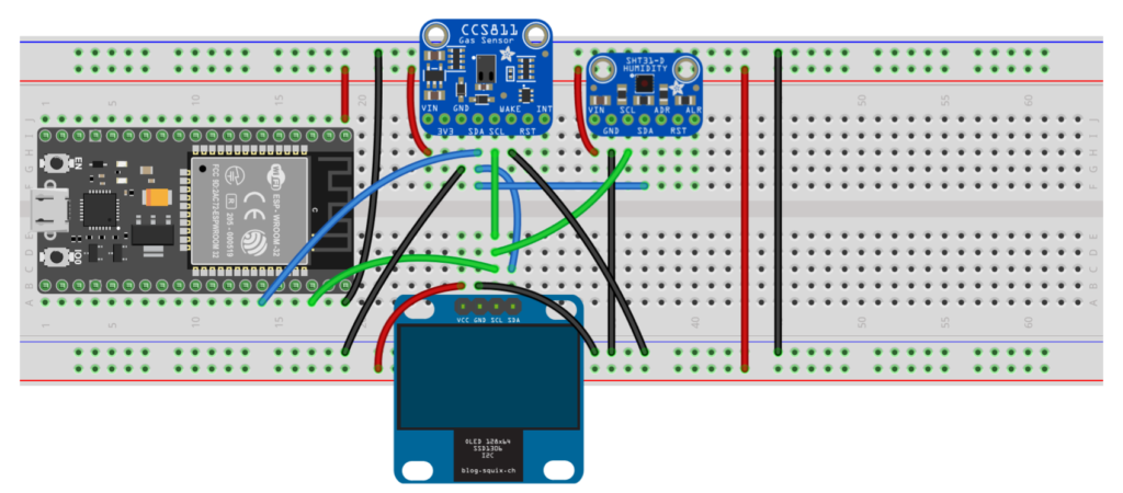
The CCS811, SHT30-D and SSD1306 modules are all 3.3V or 5V compatible, so directly connecting the 3.3V output pin on the ESP32 dev board to the VCC input of each module should pose no issue.
Signals
The SDA and SCL pins on the ESP32, which are pins 21 and 22 respectively, are connected to the SDA and SCL pins of the CCS811, SHT30-D and SSD1306 modules. They all use I2C to communicate, so they will share a common bus for their data and clock signals. The WAKE signal on the CCS811 module must be pulled down to ground in order to establish communications.
Libraries
Here are the libraries you would want to have installed to get these devices up and running quickly.
- https://github.com/adafruit/Adafruit_MQTT_Library
- https://github.com/adafruit/Adafruit_CCS811
- https://github.com/adafruit/Adafruit_SHT31
- https://github.com/ThingPulse/esp8266-oled-ssd1306
Go to Sketch->Include Library->Manage Libraries to find these libraries.
Software Setup
To use the Arduino IDE to program an ESP32, you’re going to need to add the ESP32 to the board manager of the Arduino IDE. You can accomplish this by:
- Opening the preferences window in the Arduino IDE.
- Entering https://dl.espressif.com/dl/package_esp32_index.json into the Additional Board Manager URLs field.
- Open Boards Manager from Tools > Board menu and install esp32 platform
Additionally you’ll need to change the WiFi and Adafruit IO credentials in the code to make it work.
- WLAN_SSID
- WLAN_PASS
- AIO_USERNAME
- AIO_KEY
If you want to use a different cloud service, you’ll also have to change these – consult the service provider website to determine the values you’ll use:
- AIO_SERVER
- AIO_SERVERPORT
Code
#include "WiFi.h"
#include "Adafruit_MQTT.h"
#include "Adafruit_MQTT_Client.h"
#include "Adafruit_CCS811.h"
#include "Adafruit_SHT31.h"
#include "SSD1306Wire.h" /************************* WiFi Access Point *********************************/ #define WLAN_SSID "YOUR_WIFI_SSID"
#define WLAN_PASS "YOUR_WIFI_PASSWORD" /************************* Adafruit.io Setup *********************************/ #define AIO_SERVER "io.adafruit.com"
#define AIO_SERVERPORT 1883 // use 8883 for SSL
#define AIO_USERNAME "INSERT_YOUR_USERNAME_HERE"
#define AIO_KEY "INSERT_YOUR_KEY_HERE" /************************* Setup *********************************/
WiFiClient client;
Adafruit_MQTT_Client mqtt(&client, AIO_SERVER, AIO_SERVERPORT, AIO_USERNAME, AIO_KEY); /****************************** Feeds ***************************************/
Adafruit_MQTT_Publish eCO2_feed = Adafruit_MQTT_Publish(&mqtt, AIO_USERNAME "/feeds/eco2");
Adafruit_MQTT_Publish TVOC_feed = Adafruit_MQTT_Publish(&mqtt, AIO_USERNAME "/feeds/tvoc");
Adafruit_MQTT_Publish temp_feed = Adafruit_MQTT_Publish(&mqtt, AIO_USERNAME "/feeds/temp"); Adafruit_CCS811 ccs;
Adafruit_SHT31 sht31 = Adafruit_SHT31();
SSD1306Wire display(0x3c, 21, 22); void MQTT_connect(); void setup() { Serial.begin(9600); WiFi.begin(WLAN_SSID, WLAN_PASS); while (WiFi.status()!= WL_CONNECTED) { delay(500); Serial.print("."); } Serial.println("CCS811 test"); if(!ccs.begin()){ Serial.println("Couldn't find SHT31"); while(1); } Serial.println("SHT31 test"); if (! sht31.begin(0x44)) { // Set to 0x45 for alternate i2c addr Serial.println("Couldn't find SHT31"); while (1) delay(1); } display.init(); //calibrate temperature sensor while(!ccs.available()); float temp = sht31.readTemperature(); ccs.setTempOffset(temp - 25.0);
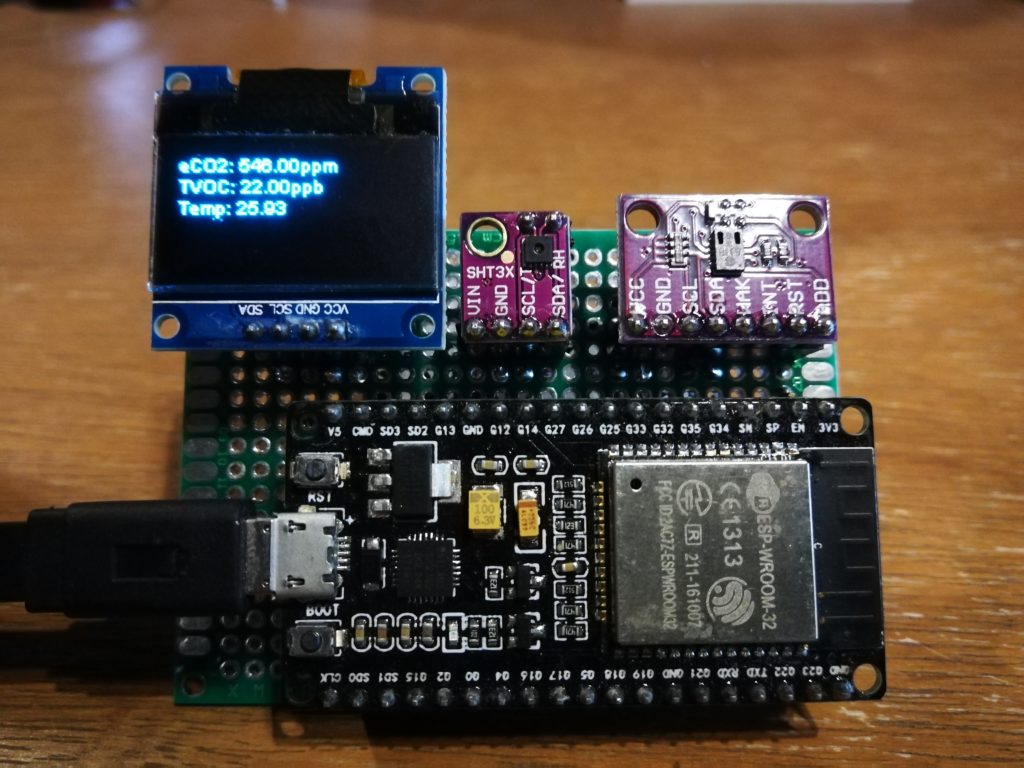
} int counter = 1; void loop() { MQTT_connect(); if(ccs.available()){ display.clear(); float temp = sht31.readTemperature(); if(!ccs.readData()){ Serial.print("eCO2: "); float eCO2 = ccs.geteCO2(); Serial.print(eCO2); display.drawString(0,0,"eCO2: " + String(eCO2) + "ppm"); display.display(); if(counter%5 == 0) //limit data usage eCO2_feed.publish(eCO2); Serial.print("ppm, TVOC: "); float TVOC = ccs.getTVOC(); Serial.print(TVOC); display.drawString(0,12,"TVOC: " + String(TVOC) + "ppb"); display.display(); if(counter%6 == 0) //limit data usage TVOC_feed.publish(TVOC); Serial.print("ppb Temp:"); Serial.println(temp); display.drawString(0,24,"Temp: " + String(temp)); display.display(); if(counter%7 == 0) //limit data usage temp_feed.publish(temp); } else{ Serial.println("ERROR!"); while(1); } } counter++; if(counter > 11) counter = 1; delay(1000);
} void MQTT_connect() { int8_t ret; // Stop if already connected. if (mqtt.connected()) { return; } Serial.print("Connecting to MQTT... "); uint8_t retries = 3; while ((ret = mqtt.connect())!= 0) { // connect will return 0 for connected Serial.println(mqtt.connectErrorString(ret)); Serial.println("Retrying MQTT connection in 5 seconds..."); mqtt.disconnect(); delay(5000); // wait 5 seconds retries--; if (retries == 0) { // basically die and wait for WDT to reset me while (1); } } Serial.println("MQTT Connected!");
}Cloud Service

You’ll want to sign up for an Adafruit IO account to follow this tutorial. A free account provides up to 30 data points per minute for 10 feeds and 5 dashboards. The code included in this tutorial limits the data point output rate to allow even free accounts to work well.
Feeds/Topics
After signing up for a free account, you should create at least 3 feeds (what Adafruit chose to call their topics), one for each sensor module. In our code, we specified three feeds:
- eco2
- tvoc
- temp
You can create a feed by hitting feeds > actions > create a new feed > create
Dashboards
Now that you have setup some feeds, you’ll want a dashboard to visualize that data.
You can do this by going to dashboards > actions > create a new dashboard > create
This will create an empty dashboard – now add some blocks by entering your dashboard, and clicking on create a new block
Choose any appropriate block type to display the data you will be receiving – I’d personally recommend a line chart in this situation.
Pick the feed you want this chart to visualize. Set labels as well as maximum and minimum values for your newly created chart, or leave them as default (you can modify this to your satisfaction later).
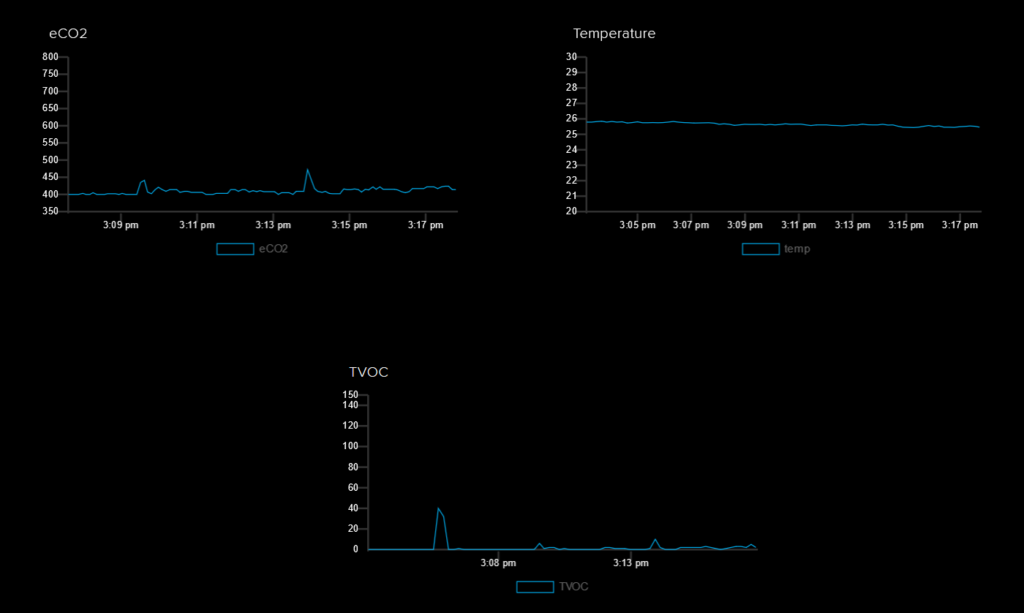
You’ll end up with a dashboard that looks like this.
That’s all folks!
The logical next step, for the more adventurous, might be to step off the perfboard and run the ICs these modules use on a PCB you would design!
Good luck, and stay creative!
Frequently Asked Questions
What does this Indoor Air Quality Monitoring with Dashboard tutorial cover?
Overview In this simple tutorial you will: Use the Arduino IDE to program an ESP32 Interface temperature, humidity and eCO2 modules to the ESP32 Output data on both a physical display, and an IOT cloud service with integrated dashboard functionality Components The ESP32 module, on its most common dev board form factor Microcontroller The ESP32 runs at 240MHz stock, is dirt cheap, and has both WiFi.
What Arduino library does the Indoor Air Quality Monitoring with Dashboard tutorial use?
The sketch uses standard Wire.h (I2C) or SPI.h plus a part-specific library installable via Arduino IDE → Sketch → Include Library → Manage Libraries. See the Sample Code section.
Why does the Indoor Air Quality Monitoring with Dashboard act differently on USB power vs battery?
Battery voltage sags under load. Add a 100uF cap across the rails, use a 5V/2A regulator-backed pack, and never power motors from the Arduino's onboard regulator.