We will show you how you can create your own self-balancing robot that can also avoid obstacle along its path. We will be using a Arduino Uno board and a MPU6050 accelerometer-gyroscope.
You will understand how the MPU6050 works with an Arduino Uno, measure the inclination angle of the robot, PID loop to make the robot stay balanced. We also added a ultrasonic sensor to serve as the ‘eye’ if an obstacle is nearby.
Components
- 1 x Arduino Uno
- 1 x Breadboard Mini
- 1 x MPU6050 Accelerometer
- 1 x L298N Motor Driver
- 2 x 18650 Battery
- 1 x 18650 Battery Holder
- 2 x DC Geared Motor with Back Shaft Straight Type
- 2 x Rubber Wheel A2WD
Connecting Everything:
The Arduino is capable of i2c communications. This is perfect since our MPU6050 accelerometer uses this. Connect SDA and SCL of MPU6050 Accelerometer to i2c pin (A4, A5) of the Arduino Uno. Also connect the VCC and GND of the MPU6050 to the 5V and GND of the Arduino Uno.

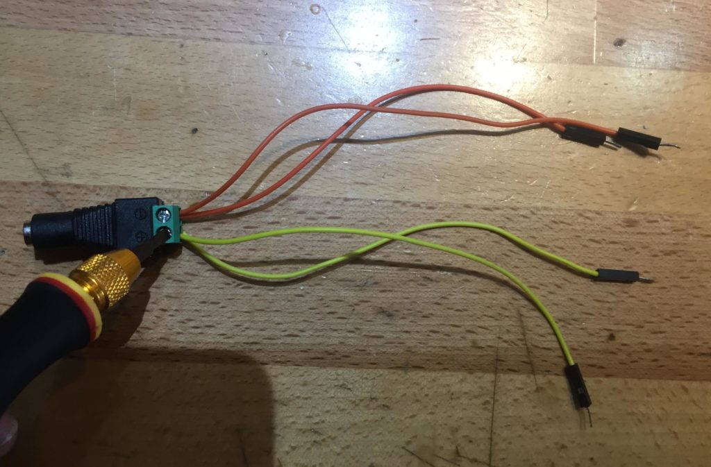
Add a DC jack Adapter with wires, connect it using screw driver. We will use this for the input power of our self balancing robot. Notice that we used two set of wires. One set is to power the Arduino uno and the DC motors. You will see this later on.
Solder the leads of the dc motor to our jumper wires and connect the other end to its corresponding motor driver.
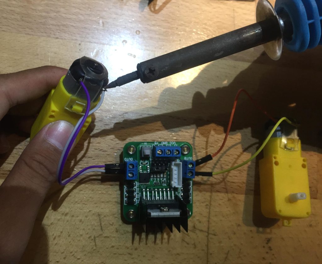
Connect the DC jack adapter to the VIN and GND of Arduino Uno and also connect it to VCC and GND of the motor driver. Make sure to follow the correct polarity. To power up the motor driver, we will get if from the 5V pin and GND of the Arduino Uno

Connect the inA, inB, inC, and inD of the motor driver to Arduino Uno. This pin is for the controls of motors.
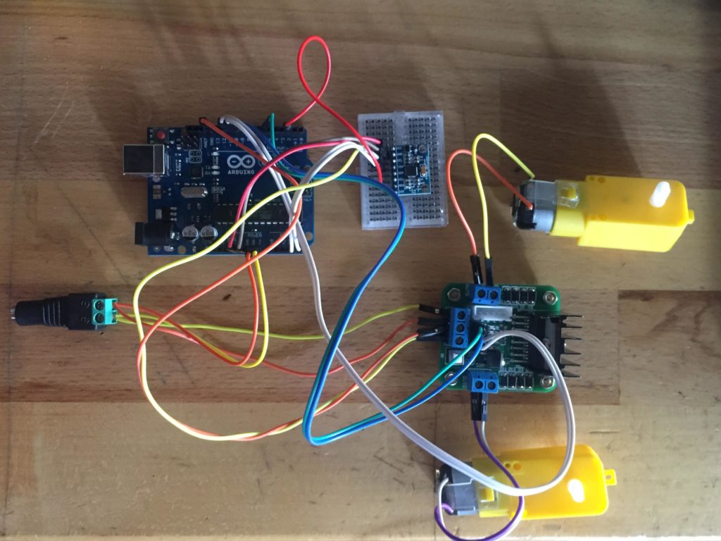
Schematic Diagram
See this schematic Diagram to double check your wirings.

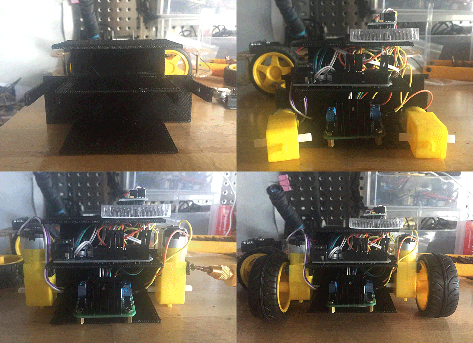
Installing it on the 3D Printed Body
Put your device inside the 3d printed case of your self balancing robot
Powering-Up
Put the 2 x 18650 battery to 18650 holder

Screws it to DC socket jack adapter. Check the polarity again.
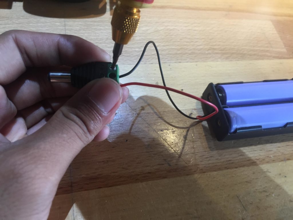
Install your battery in the 3d printed case. Plug the dc male jack adapter of battery to dc female jack adapter of your self balancing robot.
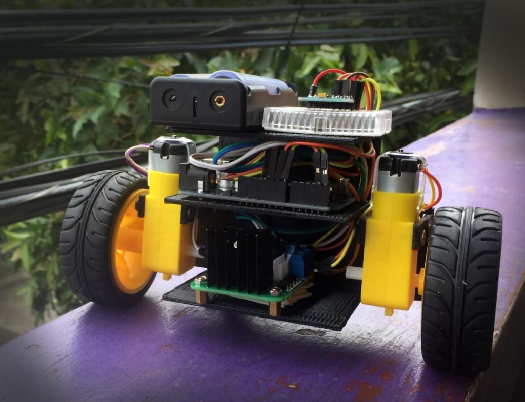
The 3D Parts
The 3D parts was create by circuit digest and you can download it here.
Code
Time to upload your code to your Arduino Uno.
#include "I2Cdev.h"
#include <PID_v1.h> //From https://github.com/br3ttb/Arduino-PID-Library/blob/master/PID_v1.h
#include "MPU6050_6Axis_MotionApps20.h" //https://github.com/jrowberg/i2cdevlib/tree/master/Arduino/MPU6050

MPU6050 mpu;

// MPU control/status vars
bool dmpReady = false;  // set true if DMP init was successful
uint8_t mpuIntStatus;   // holds actual interrupt status byte from MPU
uint8_t devStatus;      // return status after each device operation (0 = success, !0 = error)
uint16_t packetSize;    // expected DMP packet size (default is 42 bytes)
uint16_t fifoCount;     // count of all bytes currently in FIFO
uint8_t fifoBuffer[64]; // FIFO storage buffer

// orientation/motion vars
Quaternion q;           // [w, x, y, z]         quaternion container
VectorFloat gravity;    // [x, y, z]            gravity vector
float ypr[3];           // [yaw, pitch, roll]   yaw/pitch/roll container and gravity vector


/*********Tune these 4 values for your BOT*********/
double setpoint= 185; //set the value when the bot is perpendicular to ground using serial monitor.
//Read the project documentation on circuitdigest.com to learn how to set these values
double Kp = 28; //Set this first
double Kd = 0.8; //Set this secound
double Ki = 200; //Finally set this
/******End of values setting*********/

double input, output;
PID pid(&input, &output, &setpoint, Kp, Ki, Kd, DIRECT);


volatile bool mpuInterrupt = false;     // indicates whether MPU interrupt pin has gone high
void dmpDataReady()
{
    mpuInterrupt = true;
}

void setup() {
  Serial.begin(115200);

  // initialize device
    Serial.println(F("Initializing I2C devices..."));
    mpu.initialize();

     // verify connection
    Serial.println(F("Testing device connections..."));
    Serial.println(mpu.testConnection() ? F("MPU6050 connection successful") : F("MPU6050 connection failed"));

    // load and configure the DMP
    devStatus = mpu.dmpInitialize();


    // supply your own gyro offsets here, scaled for min sensitivity
    mpu.setXGyroOffset(44);
    mpu.setYGyroOffset(46);
    mpu.setZGyroOffset(8);
    mpu.setZAccelOffset(1192);

      // make sure it worked (returns 0 if so)
    if (devStatus == 0)
    {
        // turn on the DMP, now that it's ready
        Serial.println(F("Enabling DMP..."));
        mpu.setDMPEnabled(true);

        // enable Arduino interrupt detection
        Serial.println(F("Enabling interrupt detection (Arduino external interrupt 0)..."));
        attachInterrupt(0, dmpDataReady, RISING);
        mpuIntStatus = mpu.getIntStatus();

        // set our DMP Ready flag so the main loop() function knows it's okay to use it
        Serial.println(F("DMP ready! Waiting for first interrupt..."));
        dmpReady = true;

        // get expected DMP packet size for later comparison
        packetSize = mpu.dmpGetFIFOPacketSize();

        //setup PID
        pid.SetMode(AUTOMATIC);
        pid.SetSampleTime(10);
        pid.SetOutputLimits(-255, 255);
    }
    else
    {
        // ERROR!
        // 1 = initial memory load failed
        // 2 = DMP configuration updates failed
        // (if it's going to break, usually the code will be 1)
        Serial.print(F("DMP Initialization failed (code "));
        Serial.print(devStatus);
        Serial.println(F(")"));
    }

//Initialise the Motor outpu pins
    pinMode (6, OUTPUT);
    pinMode (9, OUTPUT);
    pinMode (10, OUTPUT);
    pinMode (11, OUTPUT);

//By default turn off both the motors
    analogWrite(6,LOW);
    analogWrite(9,LOW);
    analogWrite(10,LOW);
    analogWrite(11,LOW);
}


void loop() {

    // if programming failed, don't try to do anything
    if (!dmpReady) return;

    // wait for MPU interrupt or extra packet(s) available
    while (!mpuInterrupt && fifoCount < packetSize)
    {
        //no mpu data - performing PID calculations and output to motors
        pid.Compute();

        //Print the value of Input and Output on serial monitor to check how it is working.
        Serial.print(input); Serial.print(" =>"); Serial.println(output);

        if (input>150 && input<200){//If the Bot is falling

        if (output>0) //Falling towards front
        Forward(); //Rotate the wheels forward
        else if (output<0) //Falling towards back
        Reverse(); //Rotate the wheels backward
        }
        else //If Bot not falling
        Stop(); //Hold the wheels still

    }

    // reset interrupt flag and get INT_STATUS byte
    mpuInterrupt = false;
    mpuIntStatus = mpu.getIntStatus();

    // get current FIFO count
    fifoCount = mpu.getFIFOCount();

    // check for overflow (this should never happen unless our code is too inefficient)
    if ((mpuIntStatus & 0x10) || fifoCount == 1024)
    {
        // reset so we can continue cleanly
        mpu.resetFIFO();
        Serial.println(F("FIFO overflow!"));

    // otherwise, check for DMP data ready interrupt (this should happen frequently)
    }
    else if (mpuIntStatus & 0x02)
    {
        // wait for correct available data length, should be a VERY short wait
        while (fifoCount < packetSize) fifoCount = mpu.getFIFOCount();

        // read a packet from FIFO
        mpu.getFIFOBytes(fifoBuffer, packetSize);

        // track FIFO count here in case there is > 1 packet available
        // (this lets us immediately read more without waiting for an interrupt)
        fifoCount -= packetSize;

        mpu.dmpGetQuaternion(&q, fifoBuffer); //get value for q
        mpu.dmpGetGravity(&gravity, &q); //get value for gravity
        mpu.dmpGetYawPitchRoll(ypr, &q, &gravity); //get value for ypr

        input = ypr[1] * 180/M_PI + 180;

   }
}

void Forward() //Code to rotate the wheel forward
{
    analogWrite(6,output);
    analogWrite(9,0);
    analogWrite(10,output);
    analogWrite(11,0);
    Serial.print("F"); //Debugging information
}

void Reverse() //Code to rotate the wheel Backward
{
    analogWrite(6,0);
    analogWrite(9,output*-1);
    analogWrite(10,0);
    analogWrite(11,output*-1);
    Serial.print("R");
}

void Stop() //Code to stop both the wheels
{
    analogWrite(6,0);
    analogWrite(9,0);
    analogWrite(10,0);
    analogWrite(11,0);
    Serial.print("S");
}
code for Gyro Offset
// Arduino sketch that returns calibration offsets for MPU6050 //   Version 1.1  (31th January 2014)
// Done by Luis Ródenas <luisrodenaslorda@gmail.com>
// Based on the I2Cdev library and previous work by Jeff Rowberg <jeff@rowberg.net>
// Updates (of the library) should (hopefully) always be available at https://github.com/jrowberg/i2cdevlib

// These offsets were meant to calibrate MPU6050's internal DMP, but can be also useful for reading sensors.
// The effect of temperature has not been taken into account so I can't promise that it will work if you
// calibrate indoors and then use it outdoors. Best is to calibrate and use at the same room temperature.

/* ==========  LICENSE  ==================================
 I2Cdev device library code is placed under the MIT license
 Copyright (c) 2011 Jeff Rowberg

 Permission is hereby granted, free of charge, to any person obtaining a copy
 of this software and associated documentation files (the "Software"), to deal
 in the Software without restriction, including without limitation the rights
 to use, copy, modify, merge, publish, distribute, sublicense, and/or sell
 copies of the Software, and to permit persons to whom the Software is
 furnished to do so, subject to the following conditions:

 The above copyright notice and this permission notice shall be included in
 all copies or substantial portions of the Software.

 THE SOFTWARE IS PROVIDED "AS IS", WITHOUT WARRANTY OF ANY KIND, EXPRESS OR
 IMPLIED, INCLUDING BUT NOT LIMITED TO THE WARRANTIES OF MERCHANTABILITY,
 FITNESS FOR A PARTICULAR PURPOSE AND NONINFRINGEMENT. IN NO EVENT SHALL THE
 AUTHORS OR COPYRIGHT HOLDERS BE LIABLE FOR ANY CLAIM, DAMAGES OR OTHER
 LIABILITY, WHETHER IN AN ACTION OF CONTRACT, TORT OR OTHERWISE, ARISING FROM,
 OUT OF OR IN CONNECTION WITH THE SOFTWARE OR THE USE OR OTHER DEALINGS IN
 THE SOFTWARE.
 =========================================================
 */

// I2Cdev and MPU6050 must be installed as libraries
#include "I2Cdev.h"
#include "MPU6050.h"
#include "Wire.h"

///////////////////////////////////   CONFIGURATION   /////////////////////////////
//Change this 3 variables if you want to fine tune the skecth to your needs.
int buffersize=1000;     //Amount of readings used to average, make it higher to get more precision but sketch will be slower  (default:1000)
int acel_deadzone=8;     //Acelerometer error allowed, make it lower to get more precision, but sketch may not converge  (default:8)
int giro_deadzone=1;     //Giro error allowed, make it lower to get more precision, but sketch may not converge  (default:1)

// default I2C address is 0x68
// specific I2C addresses may be passed as a parameter here
// AD0 low = 0x68 (default for InvenSense evaluation board)
// AD0 high = 0x69
//MPU6050 accelgyro;
MPU6050 accelgyro(0x68); // <-- use for AD0 high

int16_t ax, ay, az,gx, gy, gz;

int mean_ax,mean_ay,mean_az,mean_gx,mean_gy,mean_gz,state=0;
int ax_offset,ay_offset,az_offset,gx_offset,gy_offset,gz_offset;

///////////////////////////////////   SETUP   ////////////////////////////////////
void setup() {
  // join I2C bus (I2Cdev library doesn't do this automatically)
  Wire.begin();
  // COMMENT NEXT LINE IF YOU ARE USING ARDUINO DUE
  TWBR = 24; // 400kHz I2C clock (200kHz if CPU is 8MHz). Leonardo measured 250kHz.

  // initialize serial communication
  Serial.begin(115200);

  // initialize device
  accelgyro.initialize();

  // wait for ready
  while (Serial.available() && Serial.read()); // empty buffer
  while (!Serial.available()){
    Serial.println(F("Send any character to start sketch.\n"));
    delay(1500);
  }
  while (Serial.available() && Serial.read()); // empty buffer again

  // start message
  Serial.println("\nMPU6050 Calibration Sketch");
  delay(2000);
  Serial.println("\nYour MPU6050 should be placed in horizontal position, with package letters facing up. \nDon't touch it until you see a finish message.\n");
  delay(3000);
  // verify connection
  Serial.println(accelgyro.testConnection() ? "MPU6050 connection successful" : "MPU6050 connection failed");
  delay(1000);
  // reset offsets
  accelgyro.setXAccelOffset(-514);
  accelgyro.setYAccelOffset(2);
  accelgyro.setZAccelOffset(1192);
  accelgyro.setXGyroOffset(44);
  accelgyro.setYGyroOffset(46);
  accelgyro.setZGyroOffset(8);
}

///////////////////////////////////   LOOP   ////////////////////////////////////
void loop() {
  if (state==0){
    Serial.println("\nReading sensors for first time...");
    meansensors();
    state++;
    delay(1000);
  }

  if (state==1) {
    Serial.println("\nCalculating offsets...");
    calibration();
    state++;
    delay(1000);
  }

  if (state==2) {
    meansensors();
    Serial.println("\nFINISHED!");
    Serial.print("\nSensor readings with offsets:\t");
    Serial.print(mean_ax);
    Serial.print("\t");
    Serial.print(mean_ay);
    Serial.print("\t");
    Serial.print(mean_az);
    Serial.print("\t");
    Serial.print(mean_gx);
    Serial.print("\t");
    Serial.print(mean_gy);
    Serial.print("\t");
    Serial.println(mean_gz);
    Serial.print("Your offsets:\t");
    Serial.print(ax_offset);
    Serial.print("\t");
    Serial.print(ay_offset);
    Serial.print("\t");
    Serial.print(az_offset);
    Serial.print("\t");
    Serial.print(gx_offset);
    Serial.print("\t");
    Serial.print(gy_offset);
    Serial.print("\t");
    Serial.println(gz_offset);
    Serial.println("\nData is printed as: acelX acelY acelZ giroX giroY giroZ");
    Serial.println("Check that your sensor readings are close to 0 0 16384 0 0 0");
    Serial.println("If calibration was succesful write down your offsets so you can set them in your projects using something similar to mpu.setXAccelOffset(youroffset)");
    while (1);
  }
}

///////////////////////////////////   FUNCTIONS   ////////////////////////////////////
void meansensors(){
  long i=0,buff_ax=0,buff_ay=0,buff_az=0,buff_gx=0,buff_gy=0,buff_gz=0;

  while (i<(buffersize+101)){
    // read raw accel/gyro measurements from device
    accelgyro.getMotion6(&ax, &ay, &az, &gx, &gy, &gz);

    if (i>100 && i<=(buffersize+100)){ //First 100 measures are discarded
      buff_ax=buff_ax+ax;
      buff_ay=buff_ay+ay;
      buff_az=buff_az+az;
      buff_gx=buff_gx+gx;
      buff_gy=buff_gy+gy;
      buff_gz=buff_gz+gz;
    }
    if (i==(buffersize+100)){
      mean_ax=buff_ax/buffersize;
      mean_ay=buff_ay/buffersize;
      mean_az=buff_az/buffersize;
      mean_gx=buff_gx/buffersize;
      mean_gy=buff_gy/buffersize;
      mean_gz=buff_gz/buffersize;
    }
    i++;
    delay(2); //Needed so we don't get repeated measures
  }
}

void calibration(){
  ax_offset=-mean_ax/8;
  ay_offset=-mean_ay/8;
  az_offset=(16384-mean_az)/8;

  gx_offset=-mean_gx/4;
  gy_offset=-mean_gy/4;
  gz_offset=-mean_gz/4;
  while (1){
    int ready=0;
    accelgyro.setXAccelOffset(ax_offset);
    accelgyro.setYAccelOffset(ay_offset);
    accelgyro.setZAccelOffset(az_offset);

    accelgyro.setXGyroOffset(gx_offset);
    accelgyro.setYGyroOffset(gy_offset);
    accelgyro.setZGyroOffset(gz_offset);

    meansensors();
    Serial.println("...");

    if (abs(mean_ax)<=acel_deadzone) ready++;
    else ax_offset=ax_offset-mean_ax/acel_deadzone;

    if (abs(mean_ay)<=acel_deadzone) ready++;
    else ay_offset=ay_offset-mean_ay/acel_deadzone;

    if (abs(16384-mean_az)<=acel_deadzone) ready++;
    else az_offset=az_offset+(16384-mean_az)/acel_deadzone;

    if (abs(mean_gx)<=giro_deadzone) ready++;
    else gx_offset=gx_offset-mean_gx/(giro_deadzone+1);

    if (abs(mean_gy)<=giro_deadzone) ready++;
    else gy_offset=gy_offset-mean_gy/(giro_deadzone+1);

    if (abs(mean_gz)<=giro_deadzone) ready++;
    else gz_offset=gz_offset-mean_gz/(giro_deadzone+1);

    if (ready==6) break;
  }
}


