
The Automated Boom Barrier System is an easy way to control vehicle access. For example, it uses an ultrasonic distance sensor and a servo motor to open the barrier automatically when a car gets close. As a result, the system is flexible and works in many places. In addition, it is perfect for parking lots, private gates, and other entrances.
When a vehicle is detected, the system moves the servo motor to lift the barrier. Then, it lets the car pass before lowering it again. This design makes vehicle management much easier. Moreover, it reduces the need for people to open and close the gate manually. Because it controls who comes in and out, it also improves security. Finally, it helps traffic move faster by cutting down on waiting times.
The Automated Boom Barrier System is also a great way to learn about electronics and coding. For instance, you can see how sensors and motors work together. By combining simple parts, you can make a real system that solves everyday problems. Therefore, as technology keeps growing, projects like this help people build better automation tools to manage and improve our surroundings.
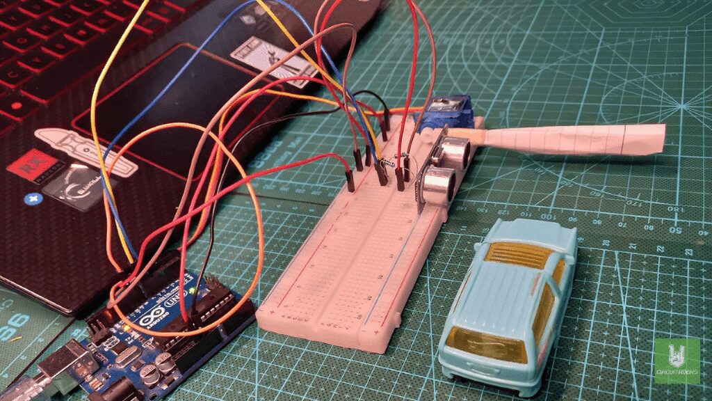
Components
Connections:
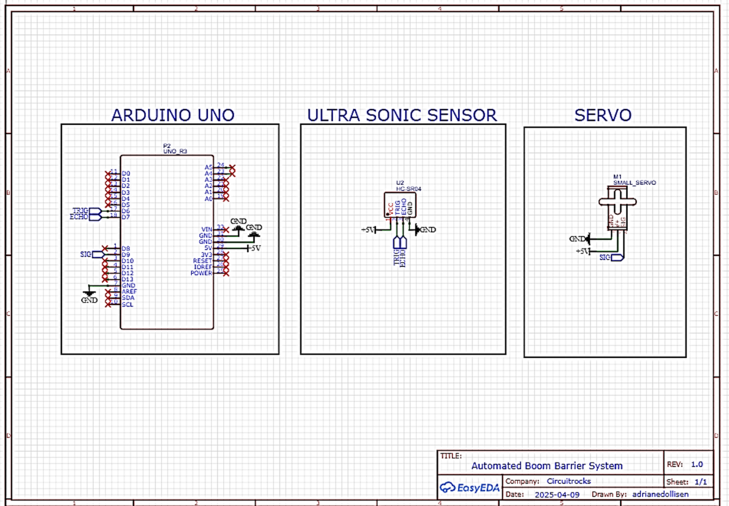
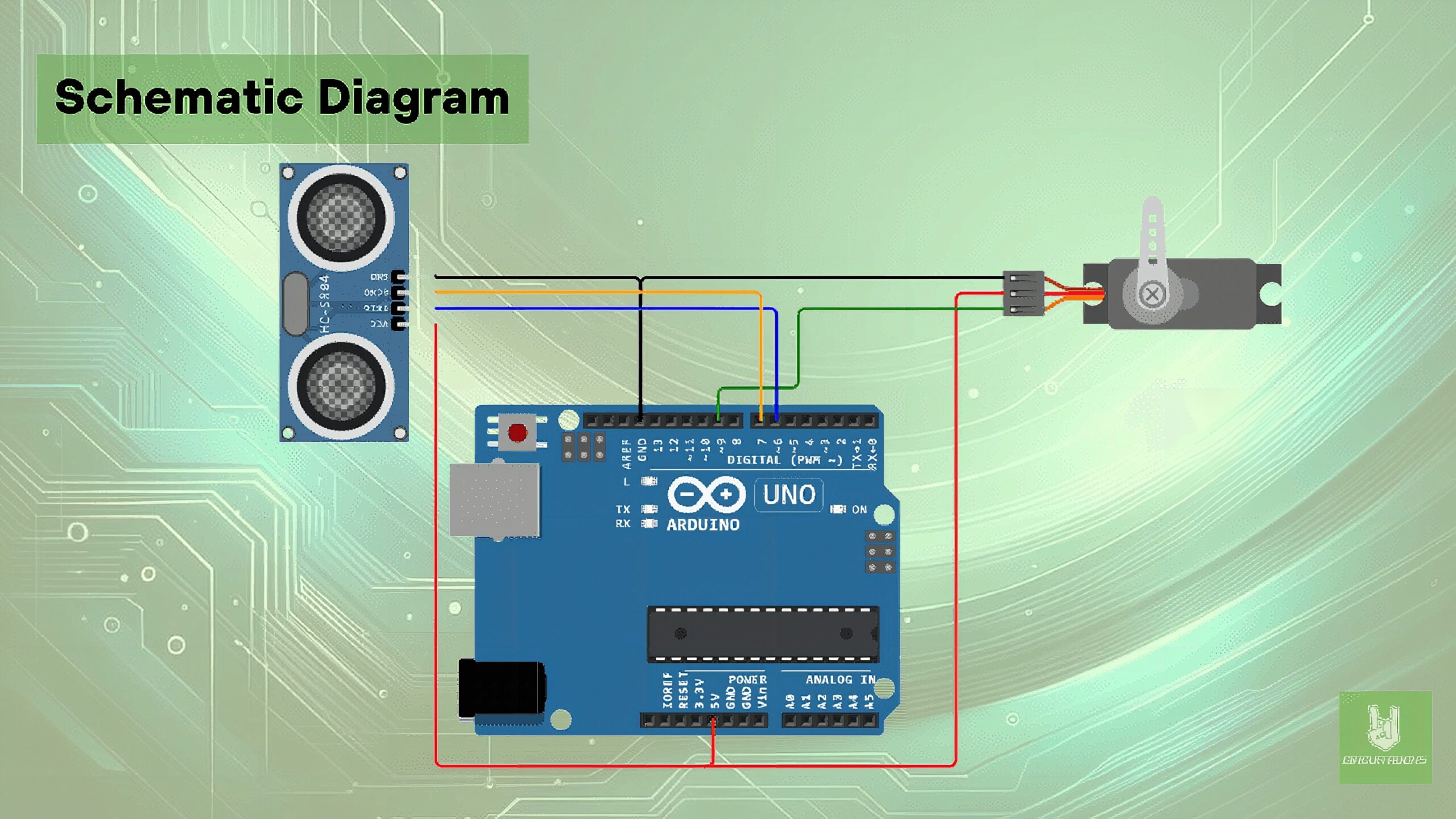
Micro Servo to Arduino:
- Signal Wire (usually orange or yellow): Connect to Digital Pin 9 on the Arduino.
- Power Wire (usually red): Connect to the 5V pin on the Arduino.
- Ground Wire (usually brown or black): Connect to one of the GND pins on the Arduino.
Ultrasonic Sensor:
- VCC: Connect to the 5V pin on the Arduino.
- Trig: Connect to Digital Pin 6 on the Arduino.
- Echo: Connect to Digital Pin 7 on the Arduino.
- GND: Connect to another GND pin on the Arduino.
Additional Notes:
- For the servo motor, it’s a good practice to use an external power source if your servo requires more current than the Arduino board can provide, to avoid damaging the board. Make sure to connect the ground of the external power source to the Arduino’s ground.
Code:
#include <Servo.h> Servo myservo; int pos = 0; int cm = 0; long readUltrasonicDistance(int triggerPin, int echoPin)
{ pinMode(triggerPin, OUTPUT); digitalWrite(triggerPin, LOW); delayMicroseconds(2); digitalWrite(triggerPin, HIGH); delayMicroseconds(10); digitalWrite(triggerPin, LOW); pinMode(echoPin, INPUT); return pulseIn(echoPin, HIGH);
} void setup() { digitalWrite(12,LOW); myservo.attach(9); Serial.begin(9600);
} void loop() { cm = 0.01723 * readUltrasonicDistance(6, 7); if(cm<5){ Serial.print(cm); Serial.println("cm"); for (pos = 0; pos <= 120; pos += 1) { myservo.write(pos); delay(15); } delay(100); for (pos = 120; pos >= 0; pos -= 1) { myservo.write(pos); delay(15); } delay(15); } }
Troubleshooting:
- Power Issues: Verify that the servo is correctly powered. If using the Arduino’s 5V, ensure it can supply adequate current. Servos under load might need more power than the Arduino can provide, necessitating an external power source.
- Code Verification: Ensure the servo control code is correctly implemented in your sketch and that there are no syntax errors.
- Sensor Alignment: Make sure the ultrasonic sensor is not obstructed and is facing the direction from which you expect objects to approach.
QUICK LINKS:
GITHUB reference
Frequently Asked Questions
What does this Automated Boom Barrier System tutorial cover?
The Automated Boom Barrier System is an easy way to control vehicle access.
What's the working voltage of the Automated Boom Barrier System?
Check the Sample Code section for the exact pinout — most maker-grade sensors run on 3.3V or 5V. Wire VCC to the matching rail, GND common with your MCU, data to a digital or analog pin.
Why does the Automated Boom Barrier System read garbage or saturated values?
Three usual causes: wrong voltage rail, missing pull-up resistor on I2C lines (4.7k–10k to VCC), or a floating data pin. Double-check wiring against the diagram, then probe with a multimeter.