

Need a big clock that is easy to read even on bright days? Why not build your own digital clock based on an ESP32. And on top update the time automatically over the internet (NTP time server).
What do we learn?
- use NeoPixel library to drive a chain of WS2812 RGBW LEDs
- how to handle multiple WiFi APs with the ESP32 MultiWiFi
- update the system time with the ESP32 internal NTP client
- use ESP32 OTA (over the air) update
What do we need?
Parts in this build
The resources
All software, spreadsheets and more can be found in our Github repo
The NeoPixelBus library can be found in the library managers of ArduinoIDE (NeoPixelBus by Makuna) or PlatformIO (NeoPixelBus by Michael Miller) or directly from Github
The hardware
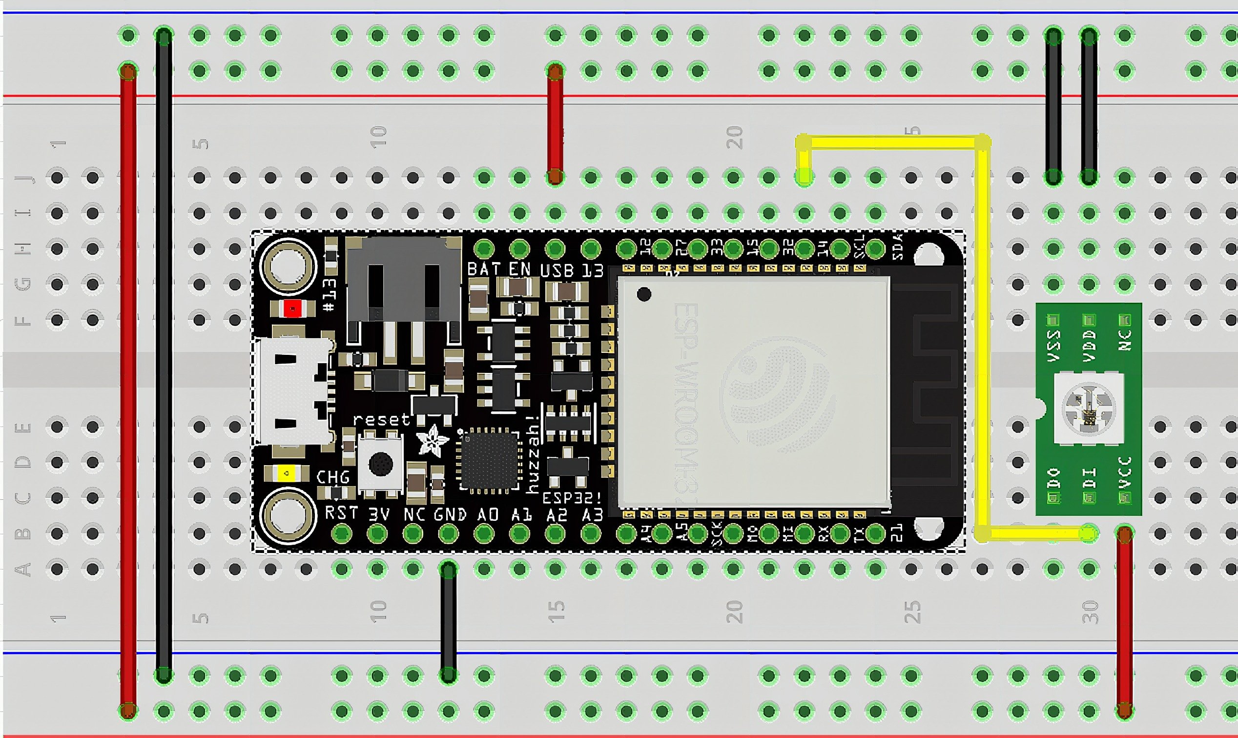
To control the WS2812 LED strips you need only one GPIO pin from the ESP32. But to supply sufficient power to light up the LED’s you need a sufficient power supply. That’s why I chose the quite powerful 2.5A RaspberryPi switching power supply.
The connections are quite easy, the power supply is plugged into the USB port of the ESP32. The LED strips power lines are connected to the 5V and GND pins of the ESP32 board. The data pin of the LED strip is connected to GPIO 14.
Preparation – how is the LED matrix built?
Before starting the software, we need to understand how the LED matrix is build. In my case it is made of 16 LED strips of 16 LEDs each. The strips are connected in a long row. It starts at the bottom left going upwards. It changes directions from left to right and then from right to left in a zig-zag scheme:
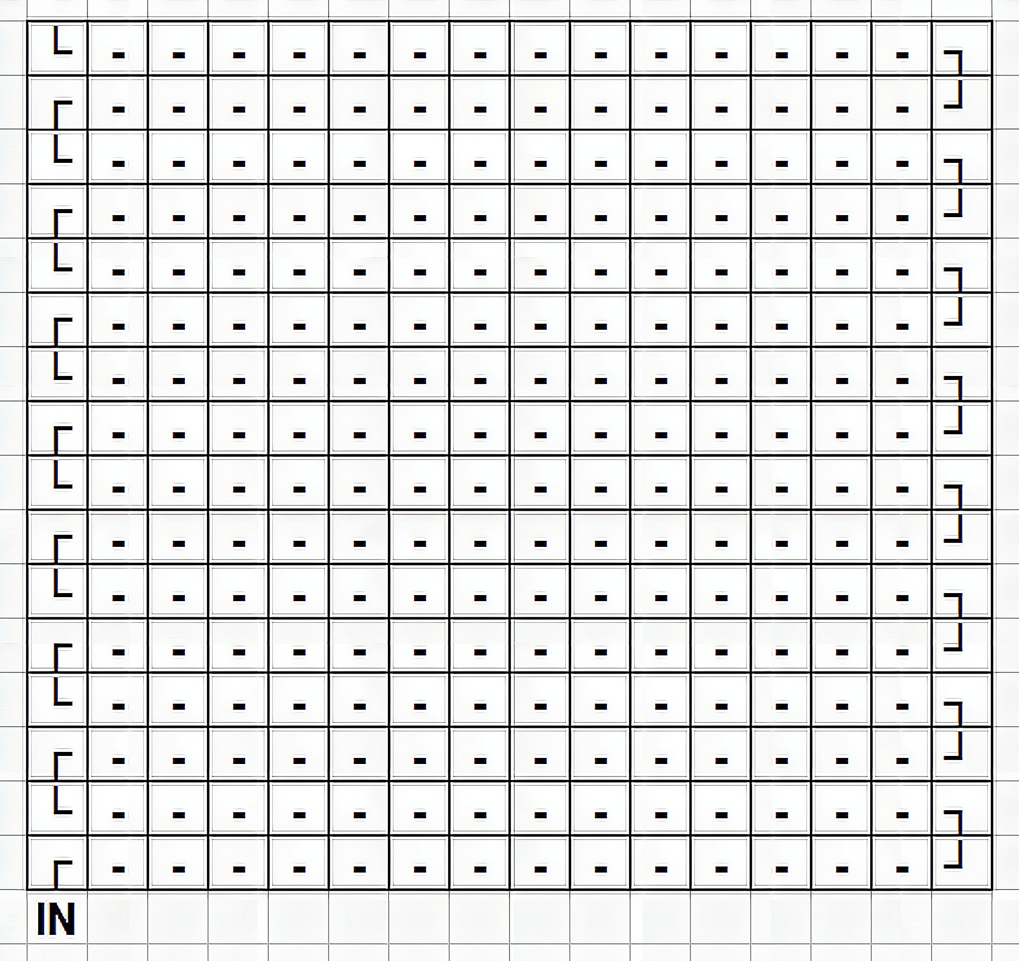
Or in pixel numbers:
Create the numbers and text
Next I designed the numbers 0 to 9 and the weekdays.

From these information I created arrays of 0’s (LED off) and 1’s (LED on) for each number and weekday. These arrays can be found in the chars.h include file in the source code. I extracted here just as an example the data for the number 0 and the weekday MON:
#include <Arduino.h>...
uint8_t n0[27] = { 0, 1, 0, 1, 0, 1, 1, 0, 1, 1, 0, 1, 1, 0, 1, 1, 0, 1, 1, 0, 1, 1, 0, 1, 0, 1, 0};...
uint8_t *number[10] = {n0, n1, n2, n3, n4, n5, n6, n7, n8, n9};...
uint8_t mon[96] = { 0,1,0,0,0,1,0,1,1,1,0,1,0,0,1,0, 0,1,0,0,1,0,1,0,1,0,1,0,0,0,1,0, 0,1,0,0,0,1,0,1,0,1,0,1,0,1,1,0, 0,1,1,0,1,0,1,0,1,0,1,0,0,0,1,0, 0,1,0,1,0,1,0,1,0,1,0,1,1,0,1,0, 0,1,0,1,1,0,1,1,1,0,1,1,0,1,1,0
};...
uint8_t *daysOfWeek[8] = {sun, mon, tue, wed, thu, fri, sat, sun};
The memory address of each number and weekday array are stored in the number and daysOfWeek arrays. This makes it easier access them later on.
The software
I will split the software explanation into 2 parts. One is about controlling the LED strips, the second one is about the WiFi stuff, OTA and NTP time updates.
Part 1 – Control the LED strips
To control the LED strips we will use the NeoPixelBus library. This makes it quite easy to send the data into the LED strips.
First we need to tell the library what RGB LEDs some information. First how many of LED’s are on the strip. Second which GPIO port is used as data port. The matrix I used has WS2812 LED chips. So we have 16×16 = 256 of them and we use GPIO 14 to send the data:
NeoPixelBus<NeoGrbFeature, NeoEsp32Rmt6Ws2812xMethod> strip(256, 14);Next some useful definitions for brightness and colors
uint8_t colorSaturation = 16; RgbColor red(colorSaturation, 0, 0);
RgbColor green(0, colorSaturation, 0);
RgbColor blue(0, 0, colorSaturation);
RgbColor white(colorSaturation);
RgbColor black(0);
For the seconds colon to blink I use the ESP32 Ticker library (build-in). The ticker is using a flag to toggle the colon on and off:
Ticker colonTicker; boolean colonVisible = false;Offsets are pre-calculated to make it simpler to handle the pixel positions for the 4 numbers of hour and minute. The offsets are for even and odd rows. And the start pixel (top left pixel of the digit) is for each digit position
int8_t evenCorr[4] = {4, 12, 22, 30};
int8_t oddCorr[4] = {28, 20, 10, 2};
uint16_t pixelStart[4] = {128, 132, 137, 141};
I will explain later how we will use these values.
Initialization of the clock control function
The initialization code is quite simple. It just calls the NeoxPixelBus start function, blanks out all pixels and starts the Ticker to blink the seconds colon:
void initClock(void)
{ strip.Begin(); strip.Show(); colonTicker.attach(0.5, setColon);
}
The library will create a buffer where the status of all LEDs is stored. To update the LED matrix we call strip.Show() which will send the buffer to the LED matrix. We do this with the function updateClock()
void updateClock(void)
{ strip.Show();
}
Writing the numbers and weekdays
Now we get into the more complicated part. Filling the buffer with the correct status of each LED.
The above defined offsets and positions are used e.g. for the tenth of an hour as following.
The top left pixel is on position 128. Index 0 of the number is copied to pixel 128. Index 1 is copied to pixel 129, index 2 to pixel 130. This first row is on a even number. The evenCorr value 4 is used to get the next pixel address. (4 because of the loop function I use, the offset is actually -3).
Then for the next row (an odd row) we copy index 3 to pixel 127. The value of index 4 is copied to pixel 126 and index 5 to pixel 125. Now we need to get the start pixel for the next row. This time we use the oddCorr value 28 to get the first pixel number of the next row. (28 because of the loop function I use, the offset is actually -29).
The code to bring the time to the matrix
The code for this is in the function setNumber. First we check if the digit we want to write is the most left (the tenth of an hour). If it is this digit and the number is 0, we just blank all pixels (using the pixel array blank). Otherwise we get the address of the array for the number we want to show
void setNumber(uint8_t value, uint8_t digit)
{ uint8_t *arrPtr; if ((digit == 0) && (value == 0)) { arrPtr = blank; } else { arrPtr = number[value]; }
Next we get the pixel number we will start from. And which even row and odd row correction values we need to use
uint8_t pixel = pixelStart[digit]; int16_t evenCorrVal = evenCorr[digit]; int16_t oddCorrVal = oddCorr[digit];Then we start a loop for the 9 rows we need to write
for (uint8_t row = 0; row < 9; row++) {And then we start a loop that will get the pixel status from the digit array. Depending on the value we set the LED on or off. And we need to handle the zig-zag going rows of the matrix. So we check if we are in an even row (pixels counting up) or in an odd row (pixels counting down)
for (uint8_t col = 0; col < 3; col++) { if (arrPtr[(row * 3) + col] == 1) { strip.SetPixelColor(pixel, green); } else { strip.SetPixelColor(pixel, black); } if (row % 2 == 0) { pixel++; } else { pixel--; } }After we have written a row, we check if we are in an even or an odd row. Depending on the result we correct the start for the next row accordingly.
 if (row % 2 == 0) { pixel -= evenCorrVal; } else { pixel -= oddCorrVal; } }
}
And that’s it for writing a number to a specific digit on the matrix.
The code to write the day of the week
For the day of week it is simpler because the weekdays are always written to the same row/column area. The arrays containing the data for the weekdays are already created handling the zig-zag going LED strips. SO here we just set all pixels in the area with the data from the day array
void setDay(uint8_t value)
{ uint8_t *day = daysOfWeek[value]; for (int pixel = 160; pixel < 256; pixel++) { if (day[pixel - 160] == 1) { strip.SetPixelColor(pixel, blue); } else { strip.SetPixelColor(pixel, black); } }
}
The next function is called every 500ms from the Ticker colonTicker. It checks if the colon pixels should go on or off. This is found by the status of the flag colonVisible, then it toggles the flag colonVisible. After that the 8 pixels of the colon are either shown or blacked out
void setColon(void)
{ RgbColor colonColor = black; if (colonVisible) { colonColor = red; } colonVisible =!colonVisible; strip.SetPixelColor(39, colonColor); strip.SetPixelColor(40, colonColor); strip.SetPixelColor(55, colonColor); strip.SetPixelColor(56, colonColor); strip.SetPixelColor(87, colonColor); strip.SetPixelColor(88, colonColor); strip.SetPixelColor(103, colonColor); strip.SetPixelColor(104, colonColor); strip.Show();
}
Dim the display
And last, as in my case I don’t need to the clock to be on for 24 hours. Even power hacker like me need some sleep;-). For this we have a function to set the brightness of each color. The control of the brightness is done from the main loop.
void setBrightness(uint8_t newBrightness)
{ colorSaturation = newBrightness; red = RgbColor(colorSaturation, 0, 0); green = RgbColor(0, colorSaturation, 0); blue = RgbColor(0, 0, colorSaturation); white = RgbColor(colorSaturation);
}
Part 2 The WiFi stuff
The internal RTC of the ESP32 is not very accurate (several seconds per day on or off). And it does not keep the time in case of brown-outs.
To avoid the problem of correcting the time every now and then, we use a Ticker. The ticker calls every 3 hours a function. This function updates the internal RTC by calling a NTP server. To be able to do so we need an internet connection. That’s no problem using the ESP32’s WiFi.
Now, just as an example I want to introduce the WiFiMulti library. Instead of just using the WiFi begin function to connect to an AP, we use the ESP32’s internal MultiWiFi library.
The MultiWiFi library is a nice tool. It is not just trying to connect to a single WiFi AP. Instead it uses a list of AP’s that we know and can connect to. The library then scans for available WiFi AP’s. If it finds an AP that is in the list, it connects to it. If it finds several AP’s from the list, it chooses the one with the strongest signal.
Isn’t that nice?
In the first step, we initialize the WiFiMulti library by giving it a list of AP’s. Instead of waiting for the library to make a connection, we use the ESP32 WiFi callbacks. The callbacks will notify the app when we have a connection or in case we get disconnected from the AP.
Now comes is a small part of code here that should not be necessary. But the current ESP32-Arduino is a little bit messed up with its WiFi library. Often ESP32’s fail to connect to an AP. By making sure we first disconnect and then re-initialize the WiFi engine I could get around that problems
The WiFiMulti code
First we need to define the WiFiMulti class and a flag that notifies us if the connection status has changed
WiFiMulti wifiMulti; /** Connection change status */
bool connStatusChanged = false;
Then we are ready to initialize the WiFiMulti
** * Initialize WiFi * - Check if WiFi credentials are stored in the preferences * - Create unique device name * - Register WiFi event callback function * - Try to connect to WiFi if credentials are available */
void initWiFi(void)
{ WiFi.disconnect(true); delay(100); WiFi.enableSTA(true); delay(100); WiFi.mode(WIFI_STA); delay(100); WiFi.onEvent(wifiEventCb);
And here comes the part where we add the list of AP’s that we know and connect to
	// Using WiFiMulti to connect to best AP wifiMulti.addAP("FIRST_AP_NAME", "FIRST_AP_PASSWORD"); wifiMulti.addAP("SECOND_AP_NAME", "SECOND_AP_PASSWORD"); // wifiMulti.addAP("THIRD_AP_NAME", "THIRD_AP_PASSWORD");
}
And that’s it. Later after all initialization is done, we just fire up the WiFiMulti library to search for available WiFi AP’s. This will connect to the AP with the strongest signal.
As I said before, instead of waiting for the WiFi to connect, we use the WiFi callbacks. They will notify the app when we get connected or disconnected
/** * @briefCallback for WiFi events */
void wifiEventCb(WiFiEvent_t event)
{ myLog_d("[WiFi-event] event: %d", event); IPAddress localIP; switch (event) { case SYSTEM_EVENT_STA_GOT_IP: connStatusChanged = true; localIP = WiFi.localIP(); myLog_d("Connected to AP: %s with IP: %d.%d.%d.%d RSSI: %d", WiFi.SSID().c_str(), localIP[0], localIP[1], localIP[2], localIP[3], WiFi.RSSI()); break; case SYSTEM_EVENT_STA_DISCONNECTED: connStatusChanged = true; myLog_e("WiFi lost connection"); break; default: break; }
}
How to update the internal time of the ESP32 from the NTP server
That is actually way easier on the ESP32 than on other micro controllers. The ESP32-Arduino framework has already integrated functions to update the internal RTC with the time from a NTP server. All we need to do is to setup our timezone and which NTP servers we want to use.
And then I use again the Ticker library. It fires up a function every 3 hours that will initiate an update of the time.
The settings in the code are for the Philippines. If you are elsewhere, you will have to update the timezone and NTP servers to match your location
/** * Initialize NTP client * @return <code>bool</code> * true if time was updated within 10 seconds */
bool initNTP()
{ getNtp.attach(3600, tryGetTime); configTzTime("UTC-8:00", "0.asia.pool.ntp.org", "1.asia.pool.ntp.org", "2.asia.pool.ntp.org"); if (getLocalTime(&timeinfo, 10000)) { // wait up to 10sec to sync return true; } return false;
}
And the function that is called automatically every 3 hours just repeats the call to update the time
/** * Try to get time from NTP server */
void tryGetTime()
{ getLocalTime(&timeinfo, 0);
}
What if we want to update the clocks software?
If you don’t want to open your nice enclosure to update your code it is not a big problem. Thanks to the OTA library of the ESP32-Arduino framework we can update our code over WiFi. All we need to do is to activate the library and call the libraries handler frequently from our main loop. Then we can start a software update OTA from the ArduinoIDE or PlatformIO. No need to take the clock from the wall and plug a USB cable in.
First we need some variables that will be used in the main loop. This is to detect if an OTA is running and to display the progress of the update
/** Flag if OTA is enabled */
boolean otaStarted = false; /** Limit the progress output on serial */
unsigned int lastProgress = 0;
Then we define the Arduino OTA callbacks. Normally you don’t need them, they are here just used to give some information about the status of the update.
ArduinoOTA // OTA request received.onStart([]() { String type; if (ArduinoOTA.getCommand() == U_FLASH) type = "sketch"; else // U_SPIFFS type = "filesystem"; // NOTE: if updating SPIFFS this would be the place to unmount SPIFFS using SPIFFS.end() Serial.println("Start updating " + type); lastProgress = 0; otaStarted = true; }).onEnd([]() { // OTA is finished Serial.println("nEnd"); }).onProgress([](unsigned int progress, unsigned int total) { // Status report during OTA if ((lastProgress == 0) || ((progress / (total / 100)) >= lastProgress + 5)) { Serial.printf("Progress: %u%%r", (progress / (total / 100))); lastProgress = (progress / (total / 100)); if (lastProgress == 0) { lastProgress = 1; } } }).onError([](ota_error_t error) { // Error occured during OTA, report it Serial.printf("Error[%u]: ", error); if (error == OTA_AUTH_ERROR) Serial.println("Auth Failed"); else if (error == OTA_BEGIN_ERROR) Serial.println("Begin Failed"); else if (error == OTA_CONNECT_ERROR) Serial.println("Connect Failed"); else if (error == OTA_RECEIVE_ERROR) Serial.println("Receive Failed"); else if (error == OTA_END_ERROR) Serial.println("End Failed"); });The important part comes now. Enabling MDNS makes sure that ArduinoIDE can see the ESP32. To be able to distinguish the right ESP32, we give it a unique name and then we initialize the OTA.
	// Enable MDNS so device can be seen ArduinoOTA.setMdnsEnabled(true); // Create a unique name char hostName[] = "PixelClock"; // Set the MDNS advertising name ArduinoOTA.setHostname(hostName); // Start the OTA server ArduinoOTA.begin();
}
Where is the rest?
As you could see in the above code snippets, I use only one include in all the files. I collect all includes and definitions for the app in one place, the main.h!
#include <Arduino.h>
#include <WiFi.h>
#include <WiFiMulti.h>
#include <Ticker.h>
#include <ArduinoOTA.h>
#include <WiFiUdp.h>
#include <ESPmDNS.h> #include <myLog.h> #include <NeoPixelBus.h> void initWiFi(void);
extern WiFiMulti wifiMulti;
extern bool connStatusChanged; void startOTA(void);
extern boolean otaStarted; /** WiFiUDP class for NTP server */
extern WiFiUDP ntpUDP;
bool initNTP(void);
void tryGetTime(void);
extern struct tm timeinfo; void initClock(void);
void updateClock(void);
void setNumber(uint8_t value, uint8_t digit);
void setDay(uint8_t day);
void setColon(void);
void setBrightness(uint8_t newBrightness);
This practice helps you in bigger projects to avoid programming mistakes. For example when you rename a variable or add/change a function used by another code block.
Last: Setup and Main loop
The setup() is quite simple. First we define a counter for failed WiFi connections. This could be used to e.g. blink a pixel on the matrix to show the connection problem. But I didn’t implement that (yet).
Then we just start the Serial interface (only needed during testing). After that the initialization routines for WiFi, NTP timeserver and clock handler are called.
#include "main.h" uint8_t noAPfound = 0; void setup()
{ Serial.begin(115200); initWiFi(); initNTP(); initClock();
}
In the (main) loop() we first fire up the WiFiMulti library to connect to an AP. It is called to try for 15 seconds to find an AP and connect to it.
void loop()
{ uint8_t multiResult = wifiMulti.run(15000U); if (multiResult!= WL_CONNECTED) { if (multiResult == WL_NO_SSID_AVAIL) { noAPfound++; if (noAPfound >= 50) { myLog_d("WiFi not connected! Error %d", multiResult); myLog_e("No WiFi AP found"); noAPfound = 0; } } else { // retry in a second delay(1000); } }
If we have a new connection, we initialize the OTA service
else { if (connStatusChanged) { startOTA(); connStatusChanged = false; } ArduinoOTA.handle(); if (otaStarted) { return; } }If an OTA update has started we should avoid any interruptions. Therefor we skip the rest of the loop here.
And the rest is just getting the time from the internal RTC and dig out the hour and number. We check as well if it makes sense to have the clock lit-up. For me there is no need to waste energy between 10pm and 7am. At these times I am not in the office. In this sleep time, the brightness of the LED’s is set to 0, which means they are off.
And last we update the clock and then send the loop() for 15 seconds into sleep. As mentioned above, the seconds colon is handled by an independant ticker.
	// Update the time time_t now; time(&now); // get time (as epoch) localtime_r(&now, &timeinfo); // update tm struct with current time // DateTime nowTime = rtc.now(); setDay(timeinfo.tm_wday == 0? 7: timeinfo.tm_wday); uint8_t nowHour = timeinfo.tm_hour; uint8_t nowMinute = timeinfo.tm_min; setNumber(nowHour / 10, 0); setNumber(nowHour - (nowHour / 10 * 10), 1); setNumber(nowMinute / 10, 2); setNumber(nowMinute - (nowMinute / 10 * 10), 3); if (nowHour >= 22) { setBrightness(0); } else if (nowHour > 7) { setBrightness(16); } updateClock(); delay(15000);
}
Frequently Asked Questions
[faq] [faq_q]How accurate is the ESP32 NTP-synced clock?[/faq_q] [faq_a]With Wi-Fi available, the ESP32 syncs to NTP servers and stays accurate to within a few hundred milliseconds. That is far better than any hardware crystal-only clock, which drifts seconds per day.[/faq_a][faq_q]What if Wi-Fi disconnects? Does the clock keep time?[/faq_q] [faq_a]Yes, the ESP32 internal RTC keeps running on its crystal oscillator. It drifts a bit (maybe 1-5 seconds per day) until Wi-Fi reconnects and a fresh NTP sync corrects it.[/faq_a][faq_q]Can I use this with an LED matrix instead of a 7-segment display?[/faq_q] [faq_a]Yes. The clock logic is the same: get the time from NTP, format it, send to display. Switch out the display library (TM1637 for 7-seg, MD_Parola for matrix). The article shows the LED matrix version.[/faq_a][faq_q]How do I handle different time zones?[/faq_q] [faq_a]The ESP32 supports POSIX time zone strings via setenv(“TZ”, “PHT-8”, 1) for Philippines time. The article includes the time zone code and how to handle daylight saving switches.[/faq_a][faq_q]What is the power consumption of a big ESP32 clock?[/faq_q] [faq_a]An LED matrix at full brightness draws 1-2 A. The ESP32 itself is a few hundred mA. Use a 5V 3A supply minimum. Dim the matrix at night to save power and reduce heat.[/faq_a][/faq]Frequently Asked Questions
What does this Make a big ESP32 digital clock tutorial cover?
Need a big clock that is easy to read even on bright days? Why not build your own digital clock based on an ESP32.
Why does my ESP32 reset randomly during the Make a big ESP32 digital clock sketch?
Usually brownout from a weak USB supply. Use a 5V/2A wall adapter or add a 470uF cap across VIN/GND. Second cause: WDT timeout — sprinkle yield() or vTaskDelay() in long loops.
Can I run ESP8266 code on an ESP32?
Mostly yes. ESP32 is API-compatible with most ESP8266 Arduino libraries plus dual core, BLE, and more I/O. Watch for analogRead range (ESP32 is 0-4095, 12-bit) and pin numbering.