
Since its inception, RFIDs are never out of trend. Applications for RFID technology include access systems, manufacturing, logistics, inventory management, retail sales and security purposes. Fortunately, it can be interfaced with Arduino as well.
Definition
RFID (Radio Frequency Identification) is a wireless communications technology wherein digital data is encoded or decoded into RFID tags via an electromagnetic field from an RFID reader/writer. Similar technologies include QR codes and Bar codes. Unlike the two though, RFID doesn’t require line of sight to be read. Data on RFID tags can also be updated real time.
The RFID system
An RFID system requires two things: A reader and a tag. The reader, also known as Proximity Coupling Device (PCD), is the base of the module. It is commonly connected to a micro controller or an Arduino. Meanwhile, the tag, also known as the Proximity Integrated Circuit Card (PICC), is where you store your data. Both RFID reader and tag contains an antenna and IC.
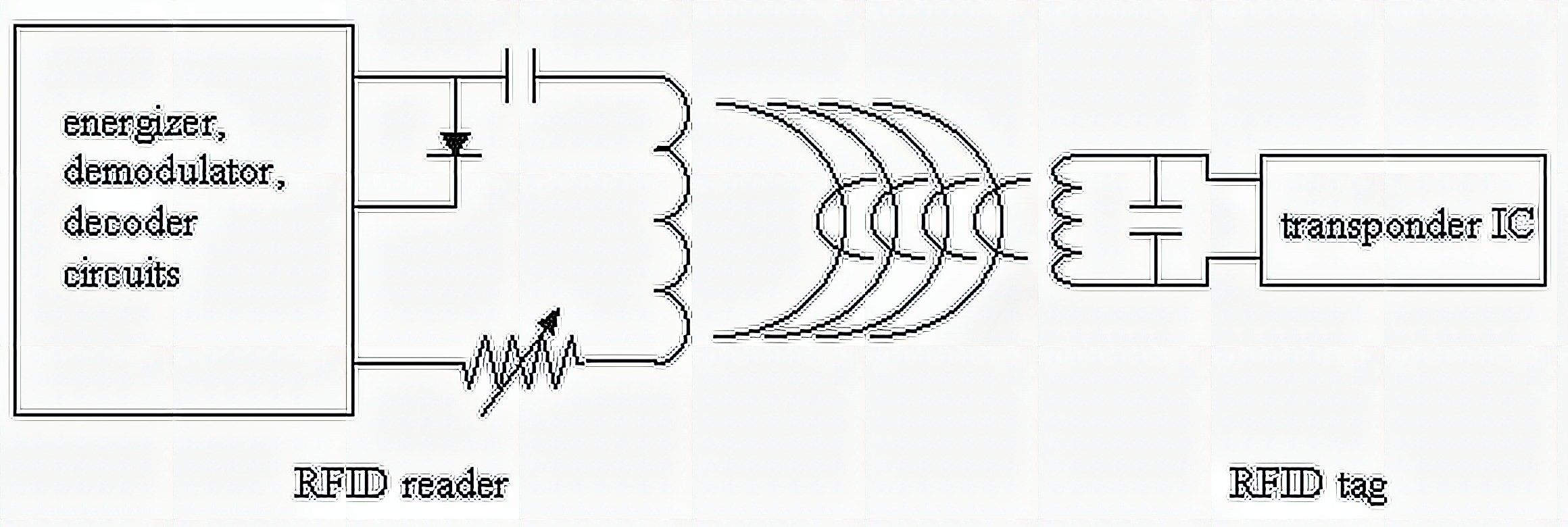
An RFID system starts with the reader IC pushing a sinusoidal current to the reader antenna. This creates an electromagnetic field around the antenna coil. Once a tag enters the EM field, the reader induces a voltage to the tag antenna. This excites the electrons to move through the tag’s antenna. As a result, current flows and powers the chip. This technology is called wireless energy transfer.
After the tag has been properly powered, it sends its stored information back to the reader. The built-in transistor shorts the coil in the form of a particular radio wave signal. This backscatter, or fluctuations in the electromagnetic wave, is decoded by the reader which then sends the data to an Arduino or a similar microcontroller.
The RC-522 RFID Module
The RC-522 RFID module is based on the MFRC522 IC from NXP. MFRC522 is a highly integrated reader/writer IC for contactless communication at 13.56 MHz. The MFRC522 reader supports ISO/IEC 14443 A/MIFARE and NTAG.

As of now, I haven’t seen an RFID module as inexpensive as this. You can buy this for less than $3 with cards included here.
The RC-522 RFID module’s operating frequency is 13.56 MHz. This means that its electromagnetic field can only activate cards with 13.56 MHz designed antennas. The reader primarily communicates with Arduino via Serial Peripheral Interface (SPI) with a maximum data rate of 10 Mbps but it also supports I2C and UART.
Supply voltage is 2.5 V to 3.6 V, minimum and maximum respectively. However, the pins are 5V tolerant so there is no need to use a logic level converter.
You can download the datasheet here:
Pinout
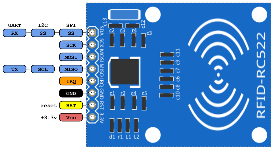
VCC – This pin supplies the power for the module. You can connect a supply voltage in the range of 2.5 – 3.6 V.
RST – This pin acts as a programmable power down circuit. When this pin receives a low, current won’t flow and all pins are virtually disconnected.
GND – This pin is the ground for the module.
IRQ – This pin is the interrupt pin. Interrupt pins alert the micro controller when a tag is present.
MISO/SCL/TX – This pin can be used for SPI MISO (Master IN Slave OUT), I2C SCL (Serial Clock) or UART TX.
MOSI – This pin can be used for SPI MOSI (Master OUT Slave IN).
SCK – This pin is for SPI SCK (Serial Clock).
SDA/SS/RX – This pin can be used for I2C SDA (Serial Data), SPI SS (Signal Input), and UART RX.
Programming with Arduino
The RC522 module can be easily interfaced with Arduino using the MFRC 522 library. You can get it through the Arduino IDE library manager or you can download it from here:
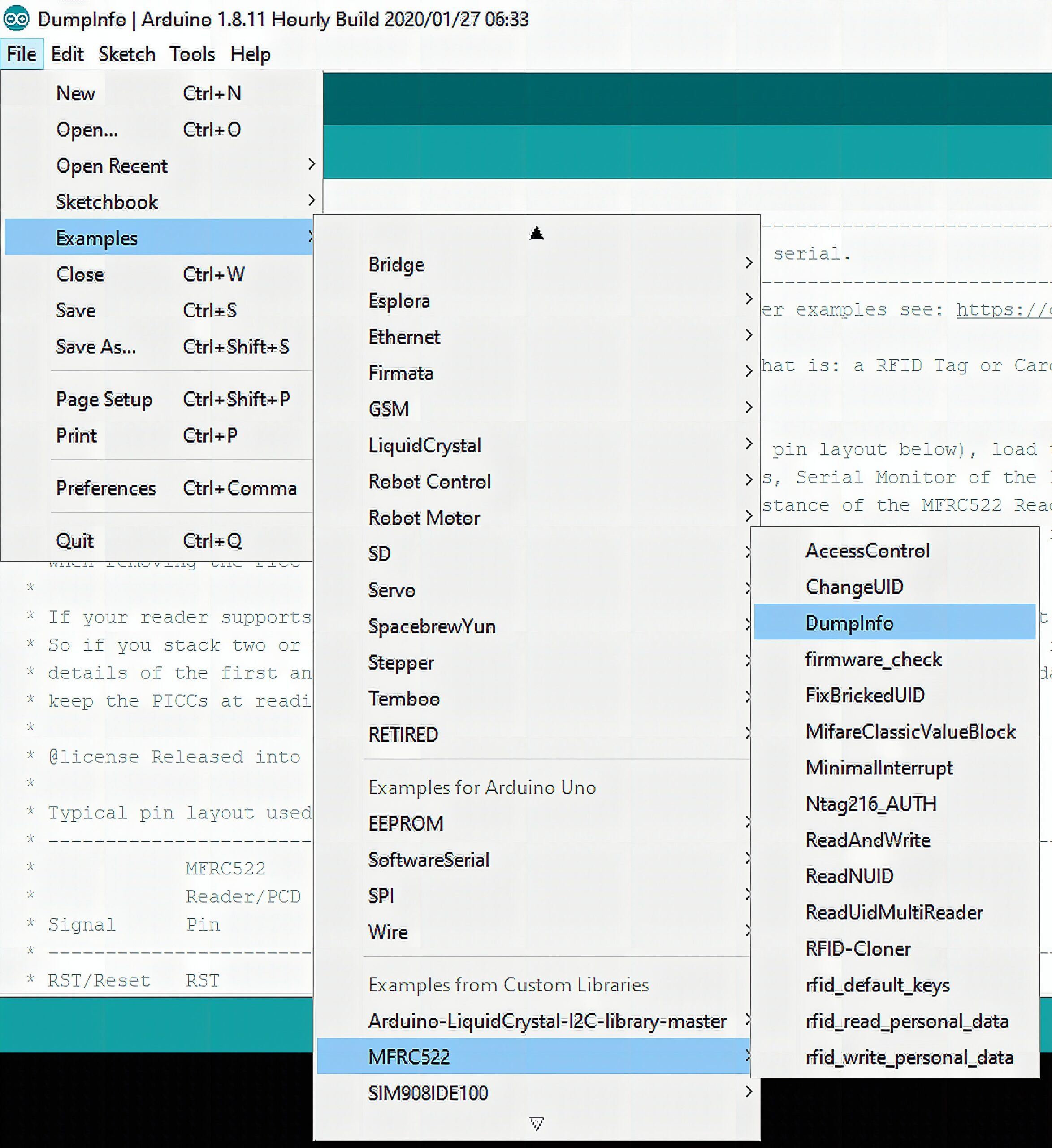
The MFRC522 library has an example that lets you see all the stored information on your PICC in the serial monitor. This sketch simply displays all of them. It won’t write anything to your card. Go to File/Examples/MFR522/DumpInfo to see.
Make sure to check your connections with the Arduino. Excluding the SPI pins, the reset and signal input pin is configurable through the DumpInfo sketch.
After you double check your connections, upload the program to the Arduino. Then, open the serial monitor. Finally, tap an RFID tag to the MFRC522 module. Do not remove the tag until the all the information is displayed.
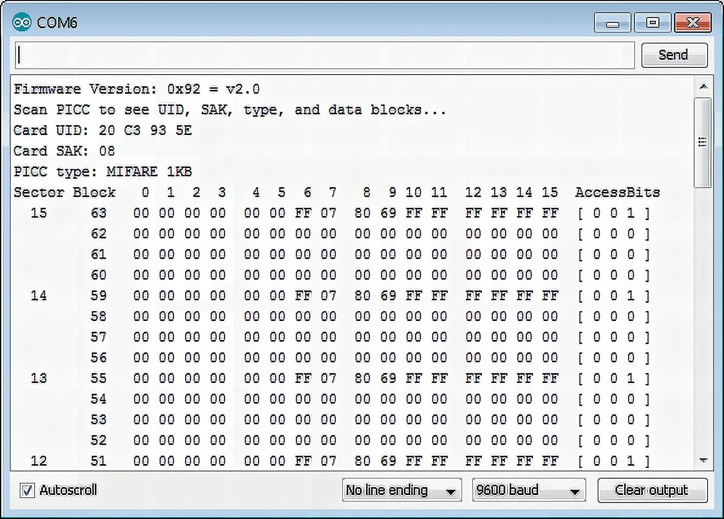
The serial monitor displays the stored information inside the RFID tag.
Tag Memory
Every RFID tag has a Unique ID (UID). Also, depending on the PICC type, a particular memory configuration. Let us take the Mifare Classic EV1 as an example. It is one of the most commonly paired RFID tag with the RC522 module.
The Mifare Classic EV1 has 1kb memory. It is organized in 16 sectors (0 to 15) with each sector divided into 4 blocks. Each block store 16 bytes of data (from 0 to 15).
Mathematically,
16 sectors x 4 blocks x 16 bytes of data = 1024 bytes = 1K memory
Here’s a visual representation of the memory:
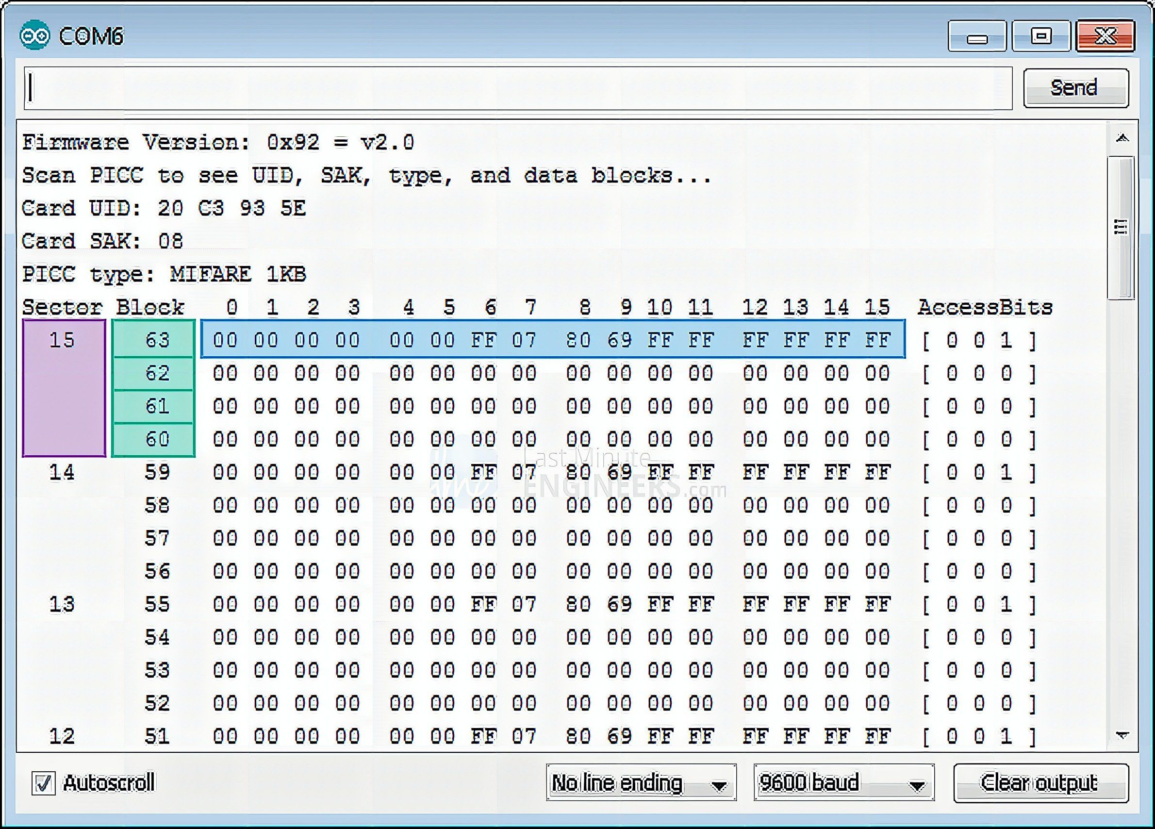
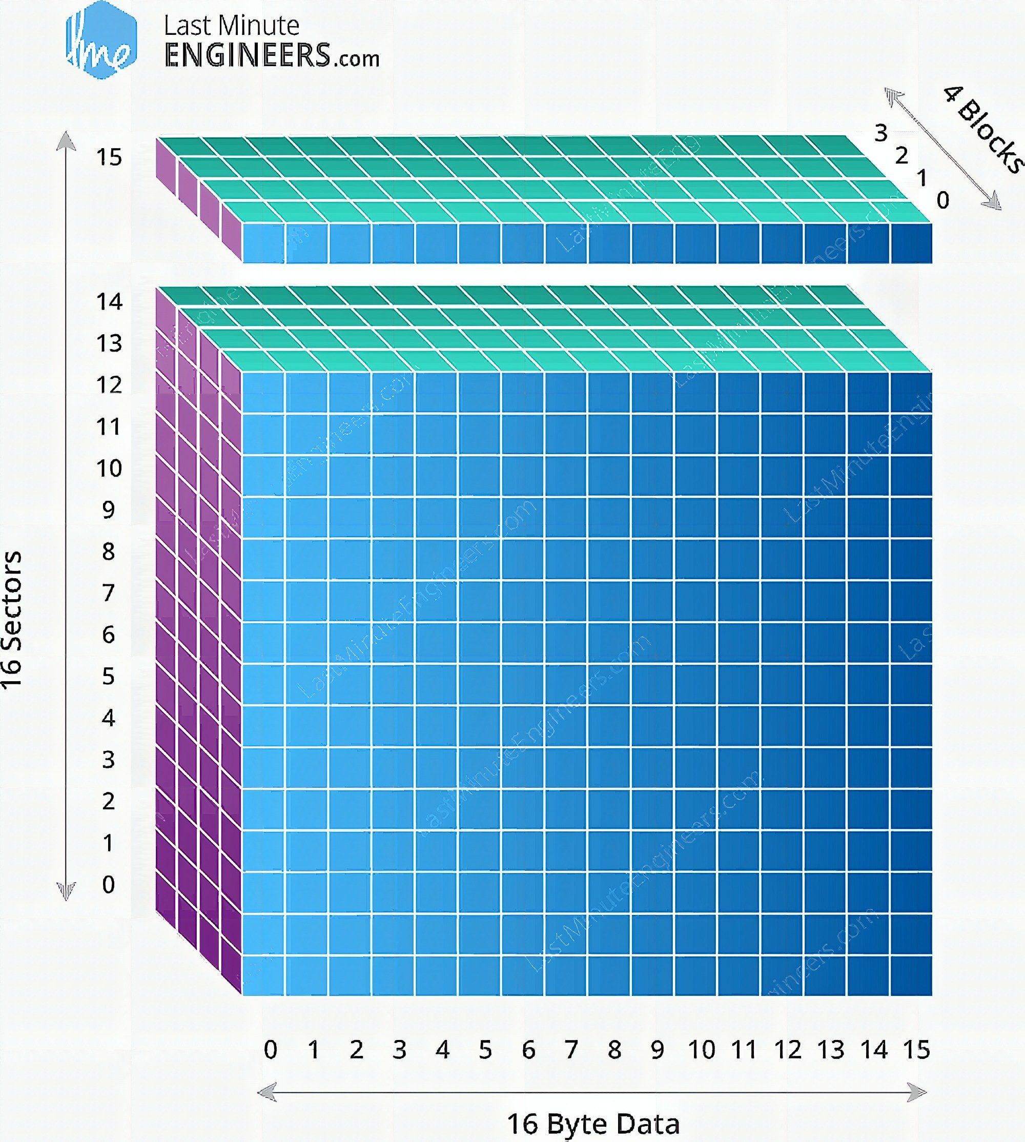
The first three blocks of a sector are available for data storage. The fourth block, known as the Sector Trailer, contains the access bits. This block holds 2 secret keys and programmable access for each.
The block 0 from sector 0 is the Manufacturer Block. It contains read-only manufacturer data. You should never try to reprogram the manufacturer block since the PICC automatically blocks the card when it detects a format violation. It is irreversible too.
Reading and Writing Tags
Copy this code:
#include <SPI.h> //include the SPI bus library
#include <MFRC522.h> //include the RFID reader library #define SS_PIN 10 //slave select pin
#define RST_PIN 5 //reset pin MFRC522 mfrc522(SS_PIN, RST_PIN); // instatiate a MFRC522 reader object.
MFRC522::MIFARE_Key key; //create a MIFARE_Key struct named 'key', which will hold the card information //this is the block number we will write into and then read.
int block=2; byte blockcontent[16] = {"Data deesired"}; //an array with 16 bytes to be written into one of the 64 card blocks is defined
//byte blockcontent[16] = {0,0,0,0,0,0,0,0,0,0,0,0,0,0,0,0}; //all zeros. This can be used to delete a block. //This array is used for reading out a block.
byte readbackblock[18]; void setup() { Serial.begin(9600); // Initialize serial communications with the PC SPI.begin(); // Init SPI bus mfrc522.PCD_Init(); // Init MFRC522 card (in case you wonder what PCD means: proximity coupling device) Serial.println("Scan a MIFARE Classic card"); // Prepare the security key for the read and write functions. for (byte i = 0; i < 6; i++) { key.keyByte[i] = 0xFF; //keyByte is defined in the "MIFARE_Key" 'struct' definition in the.h file of the library }
} void loop()
{ // Look for new cards if (! mfrc522.PICC_IsNewCardPresent()) { return; } // Select one of the cards if (! mfrc522.PICC_ReadCardSerial()) { return; } Serial.println("card selected"); //the blockcontent array is written into the card block writeBlock(block, blockcontent); //read the block back readBlock(block, readbackblock); //uncomment below line if you want to see the entire 1k memory with the block written into it. //mfrc522.PICC_DumpToSerial(&(mfrc522.uid)); //print the block contents Serial.print("read block: "); for (int j=0; j<16; j++) { Serial.write (readbackblock[j]); } Serial.println("");
} //Write specific block int writeBlock(int blockNumber, byte arrayAddress[]) { //this makes sure that we only write into data blocks. Every 4th block is a trailer block for the access/security info. int largestModulo4Number=blockNumber/4*4; int trailerBlock=largestModulo4Number+3;//determine trailer block for the sector if (blockNumber > 2 && (blockNumber+1)%4 == 0){Serial.print(blockNumber);Serial.println(" is a trailer block:");return 2;} Serial.print(blockNumber); Serial.println(" is a data block:"); //authentication of the desired block for access byte status = mfrc522.PCD_Authenticate(MFRC522::PICC_CMD_MF_AUTH_KEY_A, trailerBlock, &key, &(mfrc522.uid)); if (status!= MFRC522::STATUS_OK) { Serial.print("PCD_Authenticate() failed: "); Serial.println(mfrc522.GetStatusCodeName(status)); return 3;//return "3" as error message } //writing the block status = mfrc522.MIFARE_Write(blockNumber, arrayAddress, 16); //status = mfrc522.MIFARE_Write(9, value1Block, 16); if (status!= MFRC522::STATUS_OK) { Serial.print("MIFARE_Write() failed: "); Serial.println(mfrc522.GetStatusCodeName(status)); return 4;//return "4" as error message } Serial.println("block was written");
} //Read specific block
int readBlock(int blockNumber, byte arrayAddress[]) { int largestModulo4Number=blockNumber/4*4; int trailerBlock=largestModulo4Number+3;//determine trailer block for the sector //authentication of the desired block for access byte status = mfrc522.PCD_Authenticate(MFRC522::PICC_CMD_MF_AUTH_KEY_A, trailerBlock, &key, &(mfrc522.uid)); if (status!= MFRC522::STATUS_OK) { Serial.print("PCD_Authenticate() failed (read): "); Serial.println(mfrc522.GetStatusCodeName(status)); return 3;//return "3" as error message } //reading a block
byte buffersize = 18;//we need to define a variable with the read buffer size, since the MIFARE_Read method below needs a pointer to the variable that contains the size... status = mfrc522.MIFARE_Read(blockNumber, arrayAddress, &buffersize);//&buffersize is a pointer to the buffersize variable; MIFARE_Read requires a pointer instead of just a number if (status!= MFRC522::STATUS_OK) { Serial.print("MIFARE_read() failed: "); Serial.println(mfrc522.GetStatusCodeName(status)); return 4;//return "4" as error message } Serial.println("block was read");
}
The output should should show a scan a MIFARE classic card prompt. Followed by a card selected notification. Then the block indicator. Then the status. Finally, the output based on the written data on the desired block.
That’s it for today. Try to tinker with the code for a couple of hours. I suggest visiting this as well. See you on the next one!
Frequently Asked Questions
What does this RFID Interfacing: MFRC-522 Reader/Writer Module tutorial cover?
Since its inception, RFIDs are never out of trend.
What Arduino library does the RFID Interfacing: MFRC-522 Reader/Writer Module tutorial use?
The sketch uses standard Wire.h (I2C) or SPI.h plus a part-specific library installable via Arduino IDE → Sketch → Include Library → Manage Libraries. See the Sample Code section.
Why does the RFID Interfacing: MFRC-522 Reader/Writer Module act differently on USB power vs battery?
Battery voltage sags under load. Add a 100uF cap across the rails, use a 5V/2A regulator-backed pack, and never power motors from the Arduino's onboard regulator.