

Are you itching to connect your Arduino projects to the internet? Then this tutorial is perfect for you. In this new series of articles, we explore the well-known ESP8266 chip.
Introduction
IoT (Internet of Things) has been the buzzword, the thing for a decade now. The appeal of having your electronics talk to each other is just irresistible for consumers and technocrats alike. In fact, it is now widely used, not just in smart home systems, but with big industries like manufacturing too.
Now if you’re reading this, there’s a high chance you’ve already spent some time with DIY Arduino craft. You have probably learned how to interface sensors to an Arduino UNO and monitor them using the serial monitor. You may be wondering now, how do I put this data online? That’s exactly what the ESP8266 does.
The ESP8266
ESP8266 is a microchip made by Espressif Systems, an electronics company in Shanghai, China. The chip gives its users full WiFI networking capabilities. For instance, creating a web server.
The ESP8266 chip has three modes:
- STA Mode – In STA (Station) Mode, you set the chip to connect to a WiFi network.
- AP Mode – In AP (Access Point) Mode, you set the chip to create its own WiFi network.
- STA and AP Mode – In mode 3, the chip creates its own network but is still capable of connecting to another network.
All modes are used in different applications. For example, several ESP8266 interfaced with sensors are in mode 1 transmitting to a single ESP8266 in mode 2 that transmits the data to the web.
Popular ESP8266 Modules
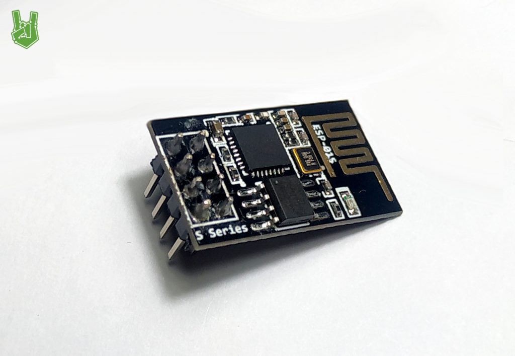
1. ESP-01
The ESP-01 module is probably the most affordable WiFi solution in existence. It has 2 GPIO pins that are perfect for simple devices like a web-based security lock.
2. WeMos D1
Next, the WeMos D1. This board is based on the ESP-8266 12-E module. Unlike the ESP-01, this has more GPIO pins ready for interfacing. It has 11 digital pins. Two of these are for serial communication and one for analog. It offers a smaller frame and lower power consumption than NodeMCU.

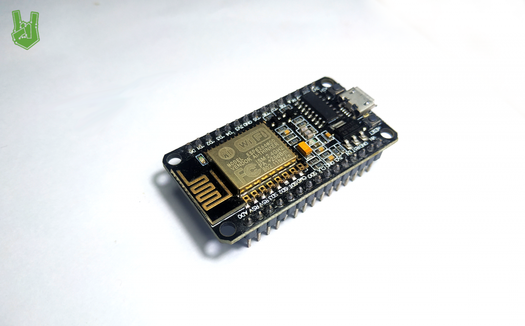
3. NodeMCU
Finally, the giant of the ESP modules: NodeMCU. This board is hailed as the best ESP platform. It is also based on the ESP8266 12-E module. It supports 12 digital pins.
Testing
For a quick demonstration of the ESP8266’s capabilities, we are going to create a simple web server that displays the room temperature using a DHT11 Temperature and Humidity sensor.
For this project, we are going to use NodeMCU. Using the ESP-01 can be tricky sometimes since you need to use an external programmer. We’ll discuss that later since that itself warrants a whole article. For now, we use NodeMCU. It’s the best ESP8266 board after all.
Parts you need:
- NodeMCU
- DHT11 Temperature and Humidity Sensor
- Breadboard
- Jumper Wires
Connect the board and the sensor using jumper wires.

The DHT11 sensor works with 3.3V and 5V so no need to worry with a separate supply.
Programming the ESP8266
In order to program the NodeMCU using the Arduino IDE, you need to do the following:
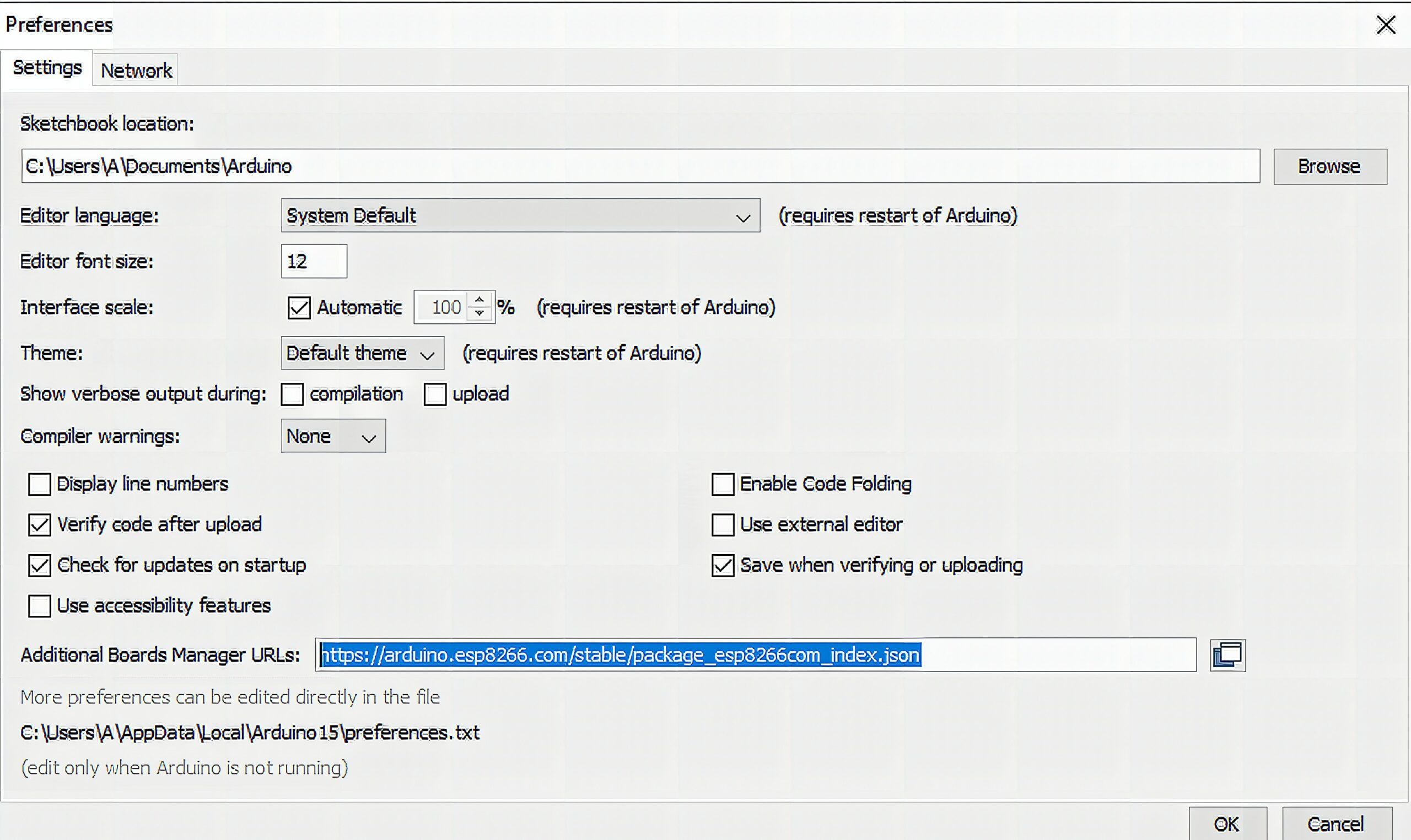
1. First, install the ESP8266 board. Go to File > Preferences.

2. In preferences, enter http://arduino.esp8266.com/stable/package_esp8266com_index.json into “Additional Boards Manager”.
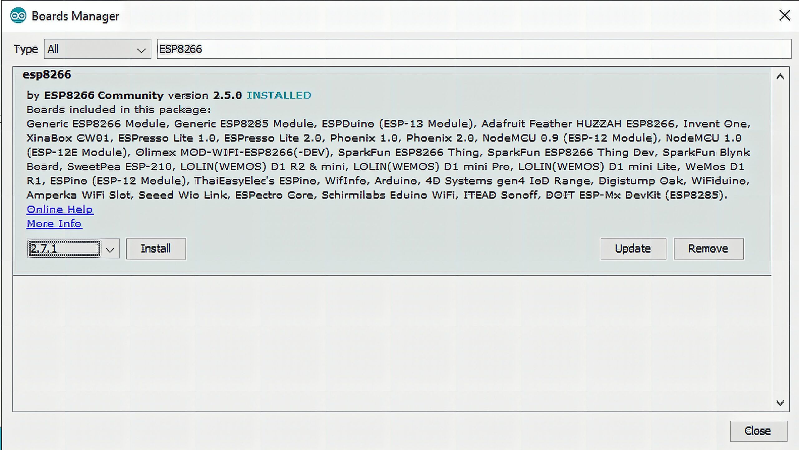
3. Next, go to Tools > Board > Boards Manager.
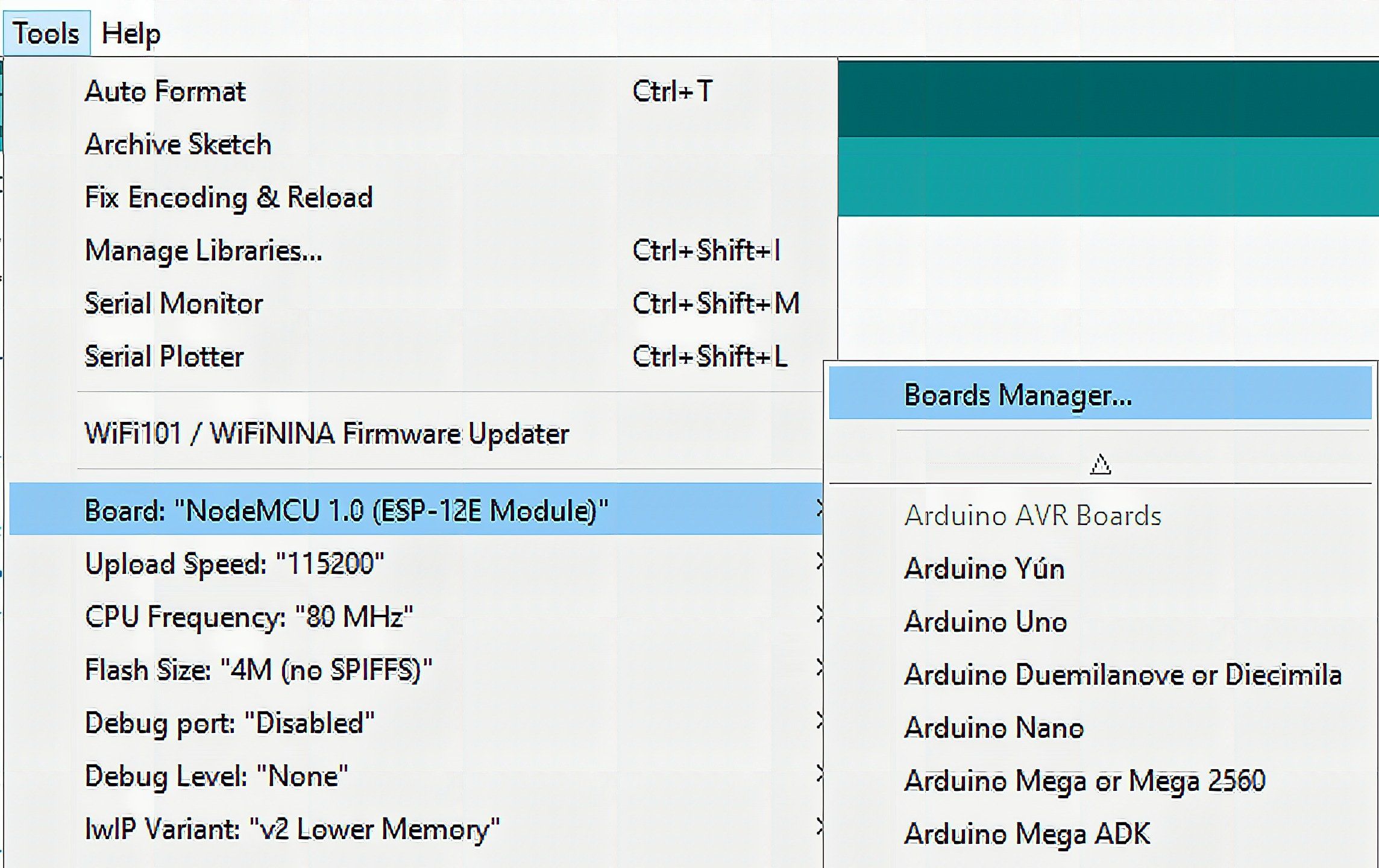
4. Finally, in Boards Manager, choose the version you want to install then click install.
Note: Libraries after the v 2.5.0 of the library have difficulties interfacing with the ESP-01 module.
By now, your Arduino IDE should program the ESP8266 chips flawlessly. All you need is the code!
Code
#include <ESP8266WiFi.h>
#include <DHT.h> #define DHTTYPE DHT22
int DHTPin = D5; DHT dht(DHTPin, DHTTYPE); const char* ssid = "WiFi Network name";
const char* password = "WiFi Password";
WiFiServer server(80); void setup() { Serial.begin(115200); pinMode(DHTPin, INPUT); dht.begin(); Serial.print("Connecting to "); Serial.println(ssid); WiFi.begin(ssid, password); while (WiFi.status()!= WL_CONNECTED) { delay(100); Serial.print("."); } Serial.println(""); Serial.println("Connected to WiFi"); Serial.print("IP: "); Serial.println(WiFi.localIP()); server.begin();
} void loop() { WiFiClient client = server.available(); if (!client) { return; } while(!client.available()){ } int Temperature = dht.readTemperature(); int Humidity = dht.readHumidity(); client.println("<!DOCTYPE HTML>"); client.println("<html>"); client.print("ESP8266 Server"); client.println("<br><br>"); client.println("Temperature: "); client.println(Temperature); client.println("C"); client.println("<br>"); client.println("Humidity: "); client.println(Humidity); client.println("%"); client.println("</html>");
}
Code Explanation
#include <ESP8266WiFi.h>
#include <DHT.h>
First, install the required libraries. ESP8266WiFi.h is a prerequisite library in any ESP board. It handles basic operations using the ESP chip. For instance, connecting to a WiFi network. Meanwhile, DHT.h is for interfacing with DHT sensors.
#define DHTTYPE DHT11
int DHTPin = D5; DHT dht(DHTPin, DHTTYPE);
Declare the DHT sensor type and the desired digital pin.
const char* ssid = "WiFi Network name";
const char* password = "WiFi Password";
WiFiServer server(80);
Enter your network credentials here to connect to your home network.
void setup() { Serial.begin(115200); pinMode(DHTPin, INPUT); dht.begin(); Serial.print("Connecting to "); Serial.println(ssid); WiFi.begin(ssid, password); while (WiFi.status()!= WL_CONNECTED) { delay(100); Serial.print("."); } Serial.println(""); Serial.println("Connected to WiFi"); Serial.print("IP: "); Serial.println(WiFi.localIP()); server.begin();
}
In the setup section, initialize the serial monitor in the ESP8266’s baud rate, 115200. Use this to confirm a successful connection and display the IP address. Initialize the server and the sensor by using dht.begin() and server.begin() respectively.
WiFiClient client = server.available(); if (!client) { return; } while(!client.available()){ }In the loop section, server.available() checks if a web client is attempting to connect to the server. While client.available() maintains the process until the connection between the server and client is lost.
client.println("<!DOCTYPE HTML>"); client.println("<html>"); client.print("ESP8266 Server"); client.println("<br><br>"); client.println("Temperature: "); client.println(Temperature); client.println("C"); client.println("<br>"); client.println("Humidity: "); client.println(Humidity); client.println("%"); client.println("</html>");Lastly, to create the web page, we use HTML programming. I made the webpage as basic as possible since HTML gets really complex, especially when paired with CSS. Here we just display the data from the sensor with some simple labels.
Demonstration
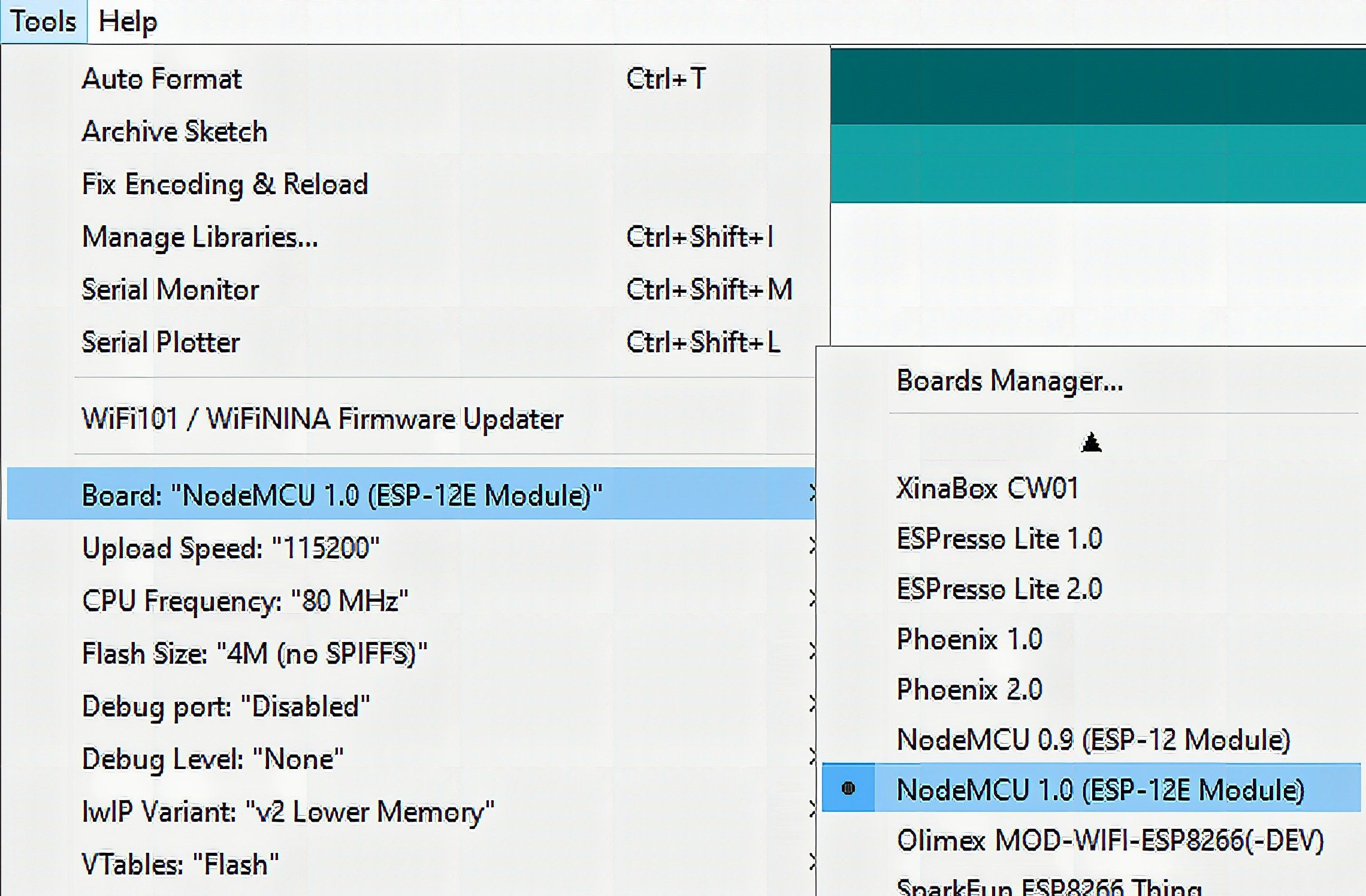
1. To demonstrate, upload the program to the ESP8266 board. Make sure to choose NodeMCU particularly. Double-check the port number as well.
2. Next, open the Serial Monitor. If the board is still not connecting to WiFi, press the RESET button on the board. Note that there may be some gibberish data at the beginning of transmission. This is due to some simple authentication done by ESP chips.
Copy the IP address from the serial monitor.

3. Last but not least, enter the IP address to your web browser.
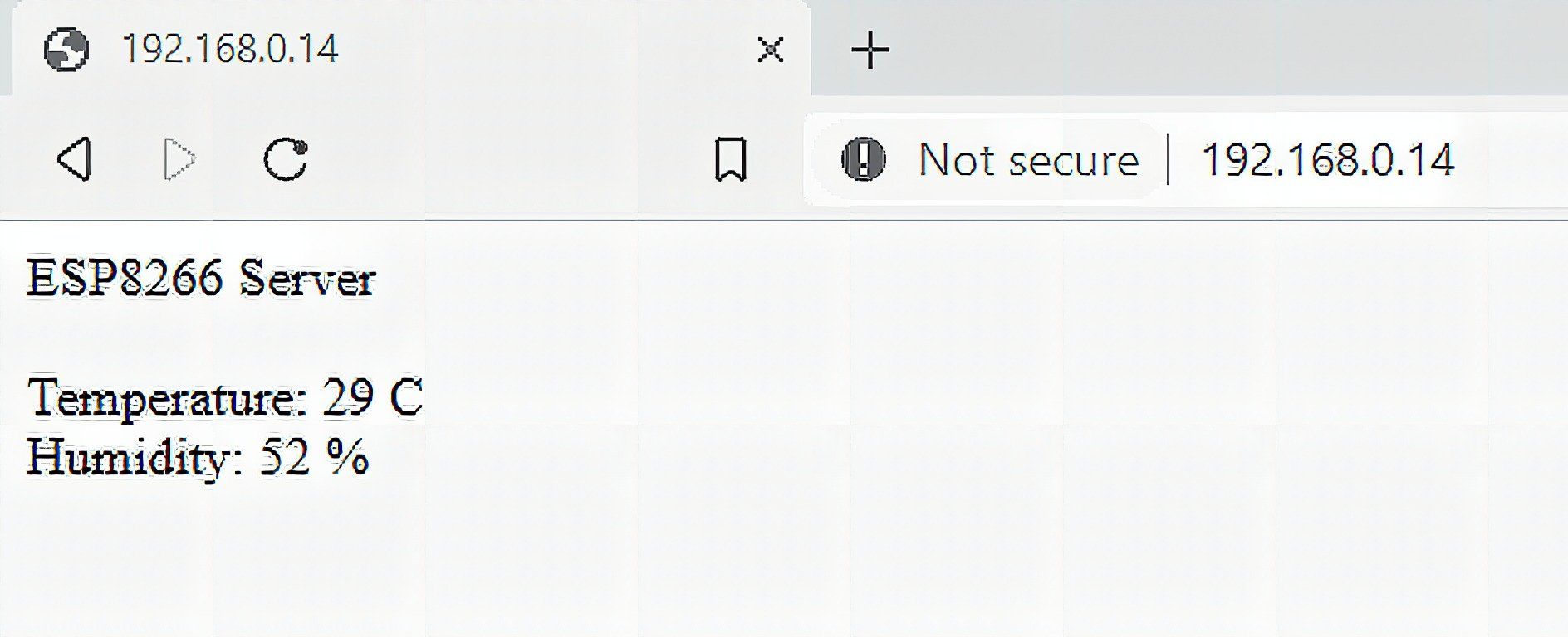
That’s it for today! Be sure to return for part 2. See you later.
Frequently Asked Questions
What does this Getting Started with the ESP8266 chip tutorial cover?
Are you itching to connect your Arduino projects to the internet? Then this tutorial is perfect for you.
What Arduino library does the Getting Started with the ESP8266 chip tutorial use?
The sketch uses standard Wire.h (I2C) or SPI.h plus a part-specific library installable via Arduino IDE → Sketch → Include Library → Manage Libraries. See the Sample Code section.
Why does the Getting Started with the ESP8266 chip act differently on USB power vs battery?
Battery voltage sags under load. Add a 100uF cap across the rails, use a 5V/2A regulator-backed pack, and never power motors from the Arduino's onboard regulator.