
In this project, I’m going to show you how to use a 3.5-inch TFT display with Arduino. It’s simple to follow, even if you’re a complete beginner. For example, I’ll walk you through every step clearly. Also, this is a great way to get started with Arduino programming. In addition, you’ll see how to create a fun bubble animation on your screen.
My goal is to help you set up the TFT display with your Arduino board easily. First, we’ll create a simple bubble animation along with a welcome message. Next, I’ll show you exactly how to connect the Arduino board to the display. As a result, you’ll know how to wire everything correctly. Because the steps are easy, even if you’re new to coding, you’ll be able to do it. Moreover, this will help you gain confidence. Finally, you’ll be ready to try even more Arduino projects on your own.
Projects like this one make hardware much easier to understand. Therefore, by following along, you’ll learn by actually doing it. Because knowing how different parts work together is important, this hands-on approach will help you practice and improve. In the end, these skills will be really useful for your journey in technology and innovation.
Components
Connection:
Directly mount it onto the Arduino board. Making the connection process very straightforward.
- Carefully align the pins on the TFT shield with the corresponding headers on the Arduino.
- Once aligned, gently press the shield down onto the Arduino until it seats securely. Make sure all pins are correctly inserted into their respective headers without bending.
Additional Notes:
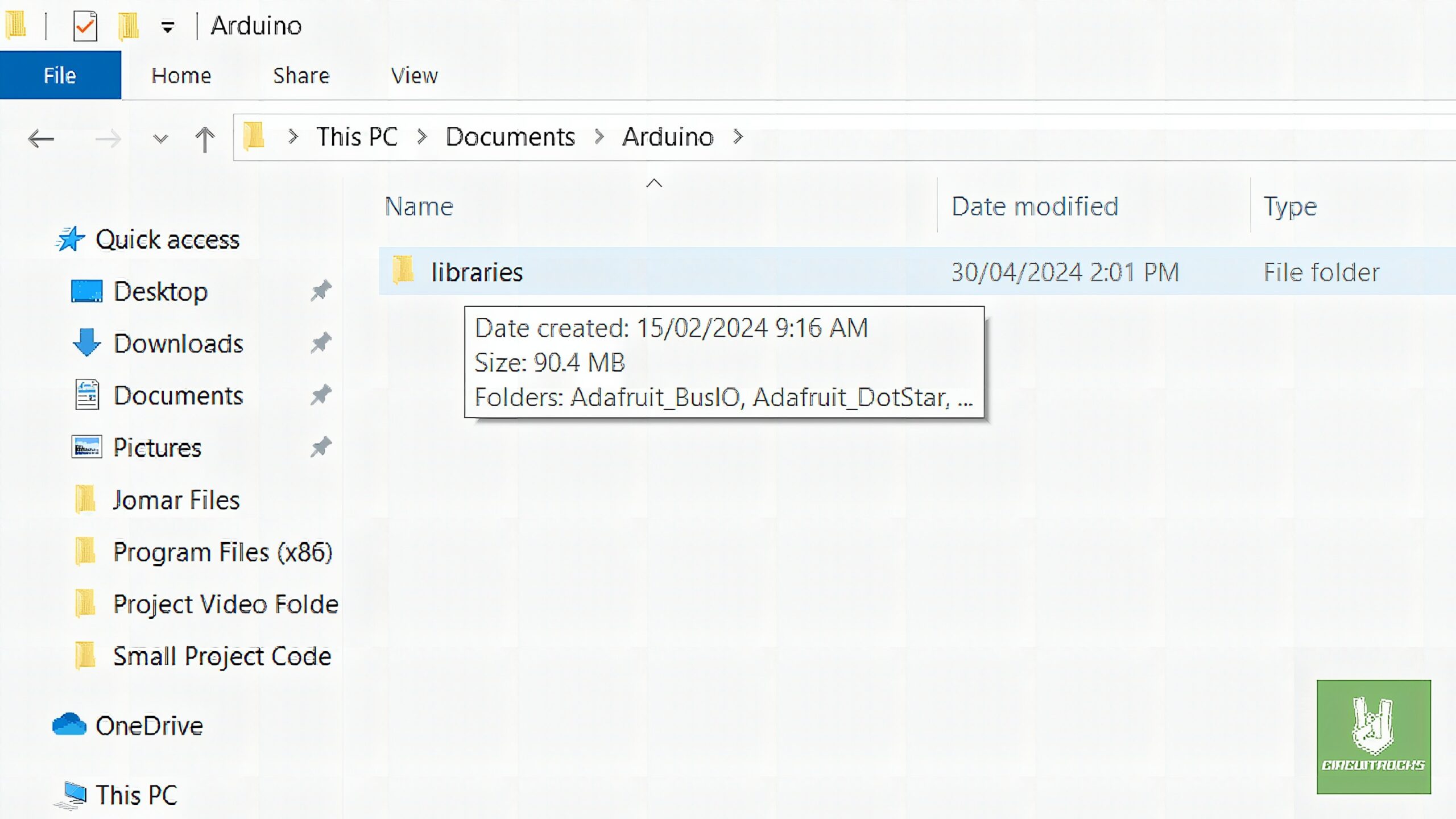
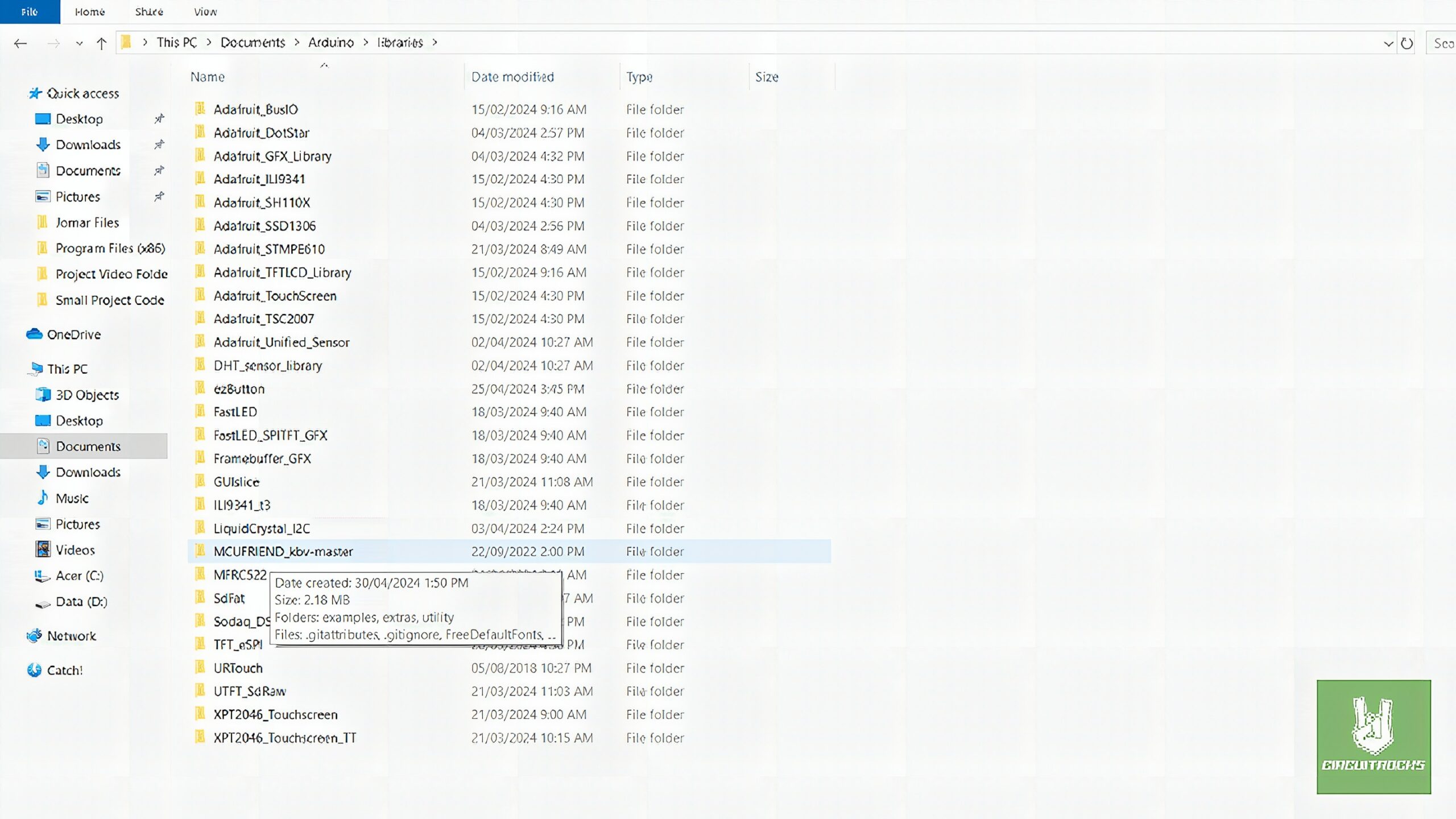
Download the library MCUFRIEND_kbv and install it manually. Insert it to the library Arduino ide.
Code:
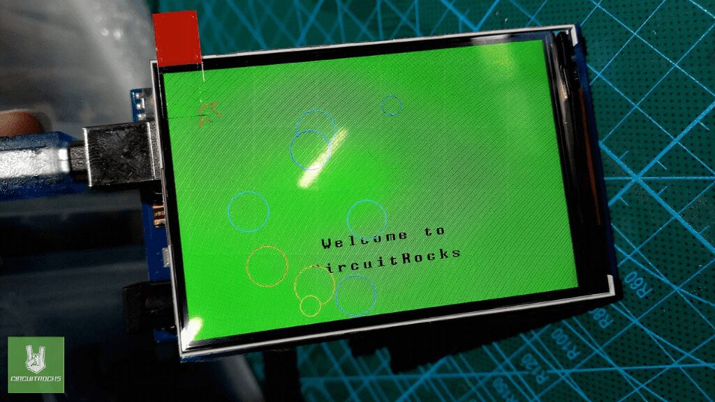
The code is written to animate the bubbles on the TFT LCD screen. By using the Arduino platform as a controller. It begins by putting the display, wiping the screen and displaying “Welcome to CircuitRocks!” welcome message.
#include <UTFTGLUE.h> // Use GLUE class and constructor
UTFTGLUE myGLCD(0,A2,A1,A3,A4,A0); // All dummy args for GLUE class struct Bubble { int x, y, radius, growthRate; word color; // Store the 16-bit color directly
}; Bubble bubbles[10]; // Array to hold multiple bubbles void setup() { randomSeed(analogRead(0)); myGLCD.InitLCD(); myGLCD.setFont(BigFont); myGLCD.clrScr(); // Clear the screen myGLCD.setBackColor(0, 255, 0); // Set background color to green myGLCD.fillScr(0, 255, 0); // Fill screen with green // Print the welcome message in the center of the screen myGLCD.setColor(0, 0, 0); // Set text color to black myGLCD.print("Welcome to", CENTER, 220); myGLCD.print("CircuitRocks", CENTER, 250); initBubbles(); // Initialize bubbles with random values
} void loop() { animateBubbles(); // Animate bubbles around the text delay(100); // Delay to control animation speed
} void initBubbles() { for (int i = 0; i < 10; i++) { bubbles[i].x = random(20, 300); bubbles[i].y = random(20, 460); bubbles[i].radius = 0; // Start with zero radius bubbles[i].growthRate = random(1, 3); // Random growth rate bubbles[i].color = HSLtoRGB(random(0, 360), 1.0, 0.5); // Assign a random hue for rainbow colors }
} void animateBubbles() { for (int i = 0; i < 10; i++) { // Erase the old bubble by redrawing it in the background color myGLCD.setColor(0, 255, 0); myGLCD.fillCircle(bubbles[i].x, bubbles[i].y, bubbles[i].radius); // Update the bubble's radius bubbles[i].radius += bubbles[i].growthRate; if (bubbles[i].radius > 30) { // Reset bubble if it gets too big bubbles[i].x = random(20, 300); bubbles[i].y = random(20, 460); bubbles[i].radius = 0; bubbles[i].growthRate = random(1, 3); bubbles[i].color = HSLtoRGB(random(0, 360), 1.0, 0.5); } // Draw the new bubble myGLCD.setColor(bubbles[i].color); myGLCD.drawCircle(bubbles[i].x, bubbles[i].y, bubbles[i].radius); }
} // Function to convert HSL to RGB and then to 16-bit color
word HSLtoRGB(float h, float s, float l) { float r, g, b; float C = (1 - fabs(2 * l - 1)) * s; float X = C * (1 - fabs(fmod(h / 60.0, 2) - 1)); float m = l - C / 2; if (h < 60) { r = C, g = X, b = 0; } else if (h < 120) { r = X, g = C, b = 0; } else if (h < 180) { r = 0, g = C, b = X; } else if (h < 240) { r = 0, g = X, b = C; } else if (h < 300) { r = X, g = 0, b = C; } else { r = C, g = 0, b = X; } // Add m to match lightness r = (r + m) * 255; g = (g + m) * 255; b = (b + m) * 255; // Convert to 16-bit color return ((uint8_t)r >> 3) << 11 | ((uint8_t)g >> 2) << 5 | ((uint8_t)b >> 3);
}
Troubleshooting:
- Verify that the pin definitions and library configurations in your sketch match the hardware setup.
- Look for any physical misalignments, bent pins, or other connection issues.
QUICK LINKS
Github library
Frequently Asked Questions
What does this Arduino TFT Bubble Welcome Screen 3.5 tutorial cover?
In this project, I’m going to show you how to use a 3.
What Arduino library does the Arduino TFT Bubble Welcome Screen 3.5 tutorial use?
The sketch uses standard Wire.h (I2C) or SPI.h plus a part-specific library installable via Arduino IDE → Sketch → Include Library → Manage Libraries. See the Sample Code section.
Why does the Arduino TFT Bubble Welcome Screen 3.5 act differently on USB power vs battery?
Battery voltage sags under load. Add a 100uF cap across the rails, use a 5V/2A regulator-backed pack, and never power motors from the Arduino's onboard regulator.