Welcome! In this guide, I’ll show you how to build the “Blinking LED with Timer Circuit.” This simple project is a great way to learn basic electronics. You’ll see how a 555 timer IC works with an LED to create a blinking effect. For example, the timer sends pulses that turn the LED on and off. In addition, you’ll get to build the circuit yourself and see how each part affects the whole system.
We’ll use the 555 timer IC in what’s called astable mode. This setup allows the timer to create continuous on-off pulses that control the LED. As a result, the LED flashes in a steady rhythm. Moreover, the resistors in the circuit set the speed of that blinking. By adjusting these resistor values, you can change how fast or slow the LED blinks. Therefore, you’ll learn how simple changes can modify the entire circuit behavior.
This blinking LED project isn’t just about making a light flash. Instead, it gives you hands-on experience with real components. Because you’re the one assembling it, you’ll see firsthand how your choices affect the outcome. Finally, by building this circuit, you’ll gain the confidence to explore even more advanced electronic projects.
Components:
The key components used in the project are a 9V battery for the power source. A two 1kΩ and a 47kΩ resistor for the frequency setting for the LED. A 2.2µF capacitor that helps to keep boundaries of the timing intervals. It produces an output that cause the LED to blink on and off.
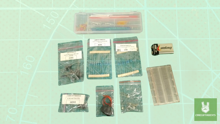
- IC 555 Timer
- U Jumper Wires
- LED
- Capacitor 2.2UF
- 1k Resistor – 2
- 47k Resistor – 1
- Battery Buckle
- 9v Battery
- Breadboard 400 Crystal
Connection:


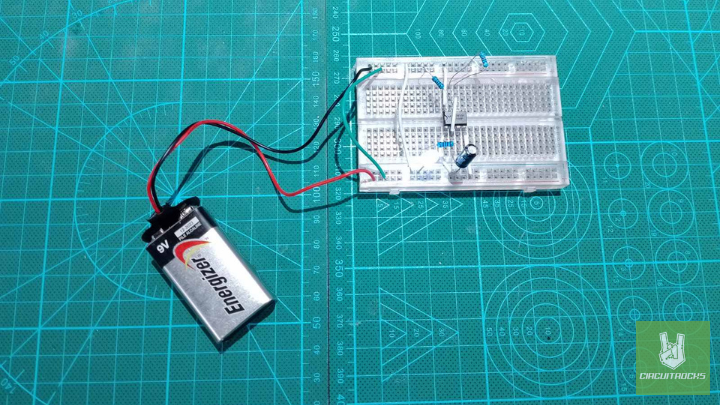
Here in this configuration, the 555 timer IC has connected in an Astable mode of 555 timer operation.
- Place the 555 timer IC onto the breadboard carefully.
- Refer to the circuit diagram to check the pin layout of the 555 timer IC.
- Next, attach pin 1 of the 555 timer IC to the ground rail. Then connect pin 8 to the positive rail on the breadboard to supply power.
- Find the polarized capacitor. The longer lead is positive (+), while the shorter lead is negative (−).
- Then, connect the positive lead to pin 2 of the 555 timer and the negative lead of the capacitor to the ground rail.
- After that, use a small jumper wire to join pin 2 and pin 6 directly on the breadboard.
- Attach a 1 kΩ resistor to pin 3 (the output pin) and connect the other end to the positive lead of the LED.
- Now, link the negative lead of the LED to the ground rail.
- Also, connect pin 4 directly to the positive rail of the breadboard.
- Leave pin 5 unconnected, as it isn’t used in this circuit.
- Finally, attach the battery’s positive and negative leads to the breadboard’s power and ground rails to power the entire circuit.
Notes:
The 555 timer IC can operate in three main modes: Astable, Monostable, and Bistable. Each mode has its specific function and setup.
1. Astable Mode (Free-running Mode)
In astable mode, the 555 timer operates as an oscillator that continuously generates a square wave without any external triggering.
2. Monostable Mode (One-shot Mode)
In monostable mode, the 555 timer produces a single pulse of fixed duration in response to an input trigger.
3. Bistable Mode (Flip-Flop Mode)
In bistable mode, the 555 timer acts as a flip-flop. Each trigger causes the output to toggle between high and low states.

