
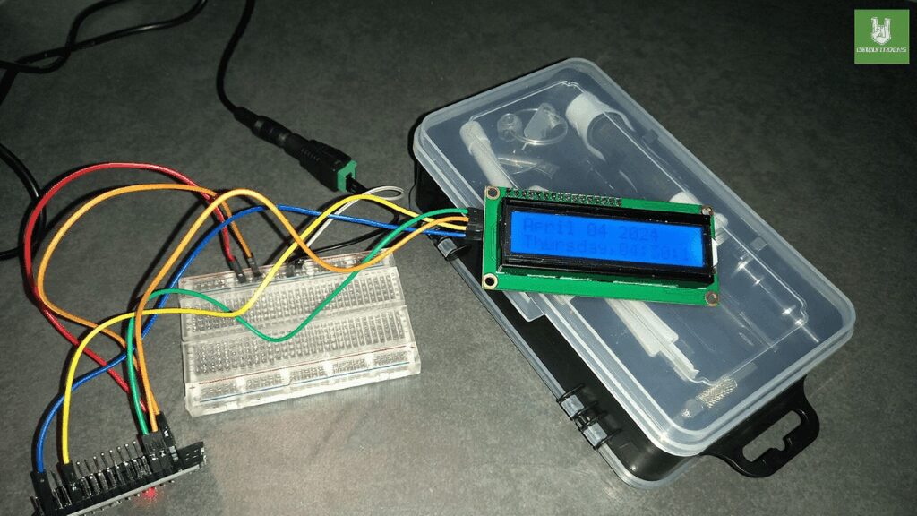
In today’s connected world, accurate time synchronization is important for many applications. For example, the ESP32 NTP Time Synchronization with LCD Display project combines two essential features: NTP (Network Time Protocol) synchronization and real-time data display on an LCD screen. Because the ESP32 can connect to internet servers for NTP, it ensures reliable timekeeping. Additionally, the LCD provides a clear and easy-to-read interface for showing synchronized time, making the system more user-friendly and accessible.
The goal of this project is to build a simple system that syncs with NTP servers and delivers precise time. First, the ESP32 connects to a WiFi network to access NTP servers. Next, it retrieves the accurate time data and updates the LCD display. As a result, users can see the current synchronized time in real-time. Moreover, this integration shows how important NTP synchronization is for many ESP32 projects and offers a great learning experience for beginners.
Finally, the project focuses on writing clear and effective code. In addition, it ensures the LCD display always shows the latest time. Because reliability and efficiency are key, the code uses a modular design for easy integration into other ESP32 projects. Therefore, anyone needing precise timekeeping can quickly adapt and expand on this system for their own needs.
Components
Connections:
Connection based on the video..
- External Power Supply Connection:
- Use a 5V 1A power supply and connect it directly to the female power adapter.
- Connect two male-to-male jumper wires to the positive and negative terminals of the female power adapter.
- Connect the other ends of these jumper wires to the positive and negative rails of a breadboard.
- Powering the ESP32 Module:
- To power the ESP32 module, use two male-to-female jumper wires.
- Connect the VIN pin of the ESP32 to the positive rail of the breadboard.
- Connect the GND pin of the ESP32 to the negative rail of the breadboard.
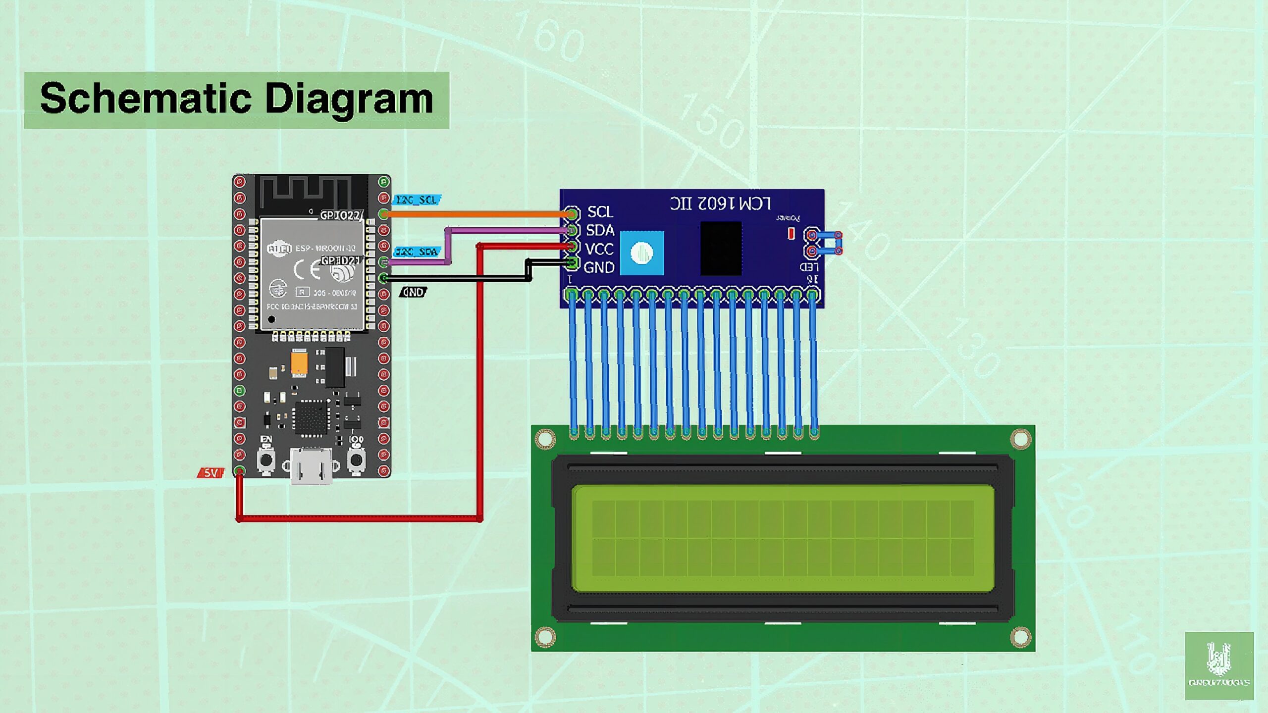
- LCD Display Connection:
- Put the VCC pin of the LCD I2C 1602 display to the 3.3V pin of the ESP32 module.
- Connect the GND pin of the LCD display to the GND pin of the ESP32 module.
- Put the SDA pin of the LCD display to pin D21 of the ESP32 module.
- Connect the SCL pin of the LCD display to pin D22 of the ESP32 module.
Notes:
- Install the “Esp32” in board manager (click the board NodeMCU-32S)
- Install the LiquidCrystal_I2C in the Library Manager
Code:
Below is a structured approach to the code for the “ESP32 NTP Time Synchronization with LCD Display” project:
#include <WiFi.h>
#include "time.h"
#include "sntp.h"
#include <LiquidCrystal_I2C.h> //0x3F or 0x27
LiquidCrystal_I2C lcd(0x3F, 16, 2); //LCD Object const char* ssid = "CIRCUIT.ROCKS";
const char* password = "abcdefghij"; const char* ntpServer1 = "pool.ntp.org";
const char* ntpServer2 = "time.nist.gov";
const long gmtOffset_sec = 3600;
const int daylightOffset_sec = 3600; void printLocalTime()
{ struct tm timeinfo; if(!getLocalTime(&timeinfo)){ Serial.println("No time available (yet)"); return; } //Display Date & Time lcd.clear(); lcd.print(&timeinfo, "%B %d %Y"); //November 22 2022 lcd.setCursor(0,1); lcd.print(&timeinfo, "%A,%H:%M:%S"); //Tuesday 10:30:05 } // Callback function (get's called when time adjusts via NTP)
void timeavailable(struct timeval *t)
{ Serial.println("Got time adjustment from NTP!"); printLocalTime();
} void setup()
{ Serial.begin(115200); // Setup LCD with backlight and initialize lcd.init(); lcd.backlight(); // set notification call-back function sntp_set_time_sync_notification_cb( timeavailable ); /** * NTP server address could be aquired via DHCP, * * NOTE: This call should be made BEFORE esp32 aquires IP address via DHCP, * otherwise SNTP option 42 would be rejected by default. * NOTE: configTime() function call if made AFTER DHCP-client run * will OVERRIDE aquired NTP server address */ sntp_servermode_dhcp(1); // (optional) /** * This will set configured ntp servers and constant TimeZone/daylightOffset * should be OK if your time zone does not need to adjust daylightOffset twice a year, * in such a case time adjustment won't be handled automagicaly. */ configTime(gmtOffset_sec, daylightOffset_sec, ntpServer1, ntpServer2); //connect to WiFi Serial.printf("Connecting to %s ", ssid); lcd.clear(); lcd.print("Connecting to "); lcd.setCursor(0, 1); lcd.print(ssid); delay(1000); WiFi.begin(ssid, password); while (WiFi.status()!= WL_CONNECTED) { delay(500); Serial.print("."); } Serial.println(" CONNECTED"); lcd.clear(); lcd.print("CONNECTED"); delay(2000);
} void loop()
{ delay(1000); printLocalTime(); // it will take some time to sync time:)
}
This structured code follows a step-by-step approach:
- Wi-Fi Setup: Connects to the specified Wi-Fi network.
- NTP Server Configuration: Sets up the NTP client with the chosen server and time zone offset.
- Initialization: Initializes the LCD display.
- Main Loop:
- Updates and displays the time in a continuous loop.
- Connect to Wi-Fi Function: Handles connecting to the specified Wi-Fi network.
- Update Time Function: Initializes the NTP client and updates the time.
- Display Time Function: Updates the time and formats it for display on the LCD.
- Format Time Function: Formats the time according to the desired format.
Troubleshooting:
- Verify that the library is installed correctly in your Arduino IDE.
- Ensure all connections are correctly made according to the instructions.
- If the LCD display is not lighting up or showing any characters, check the power supply connections and voltage levels. ( Note: Try to connect the VCC pin to the positive rail and GND pin to the negative rail of Breadboard directly to ensure sufficient power from the external power supply).
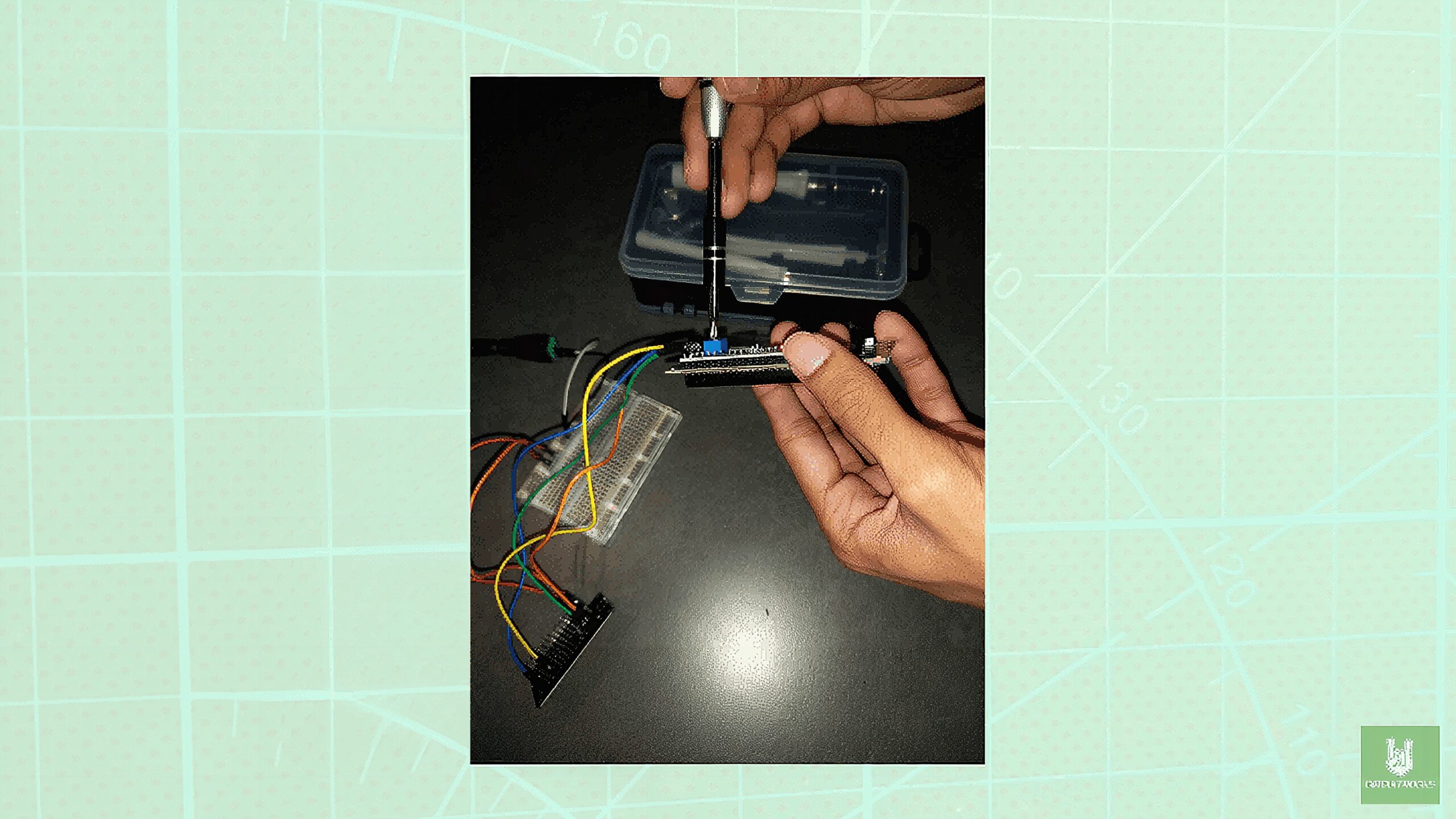
- If the text on the LCD display is not showing correctly, use a small screwdriver to carefully turn the potentiometer. Turning it clockwise or counterclockwise should change the contrast of the characters on the display.
- Look for any error messages or warnings displayed in the Arduino IDE’s Serial Monitor.
QUICK LINKS
GITHUB reference
Frequently Asked Questions
What does this ESP32 NTP Time Synchronization with LCD Display tutorial cover?
In today’s connected world, accurate time synchronization is important for many applications.
Why does my ESP32 reset randomly during the ESP32 NTP Time Synchronization with LCD Display sketch?
Usually brownout from a weak USB supply. Use a 5V/2A wall adapter or add a 470uF cap across VIN/GND. Second cause: WDT timeout — sprinkle yield() or vTaskDelay() in long loops.
Can I run ESP8266 code on an ESP32?
Mostly yes. ESP32 is API-compatible with most ESP8266 Arduino libraries plus dual core, BLE, and more I/O. Watch for analogRead range (ESP32 is 0-4095, 12-bit) and pin numbering.