
Learning how a parallel circuit works is an important first step in studying electronics. First, a parallel circuit is one of the most popular and widely used types. For example, it is helpful for students who are new to electronics and want some practical experience. Therefore, the knowledge in this guide will give you a solid foundation to build on.
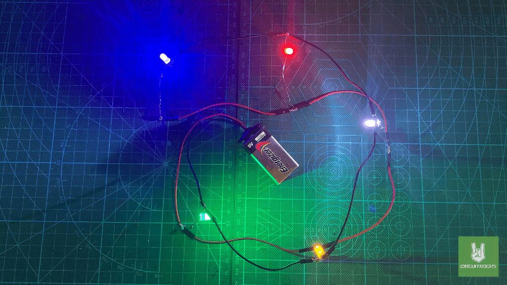
Next, the aim of the parallel circuit is to show how components can be connected. In this setup, several light sources work independently of each other. As a result, each LED operates on its own path. In addition, this circuit’s construction will help you learn how to calculate the correct resistor values for LEDs. This way, you can ensure the right brightness and safe current levels.
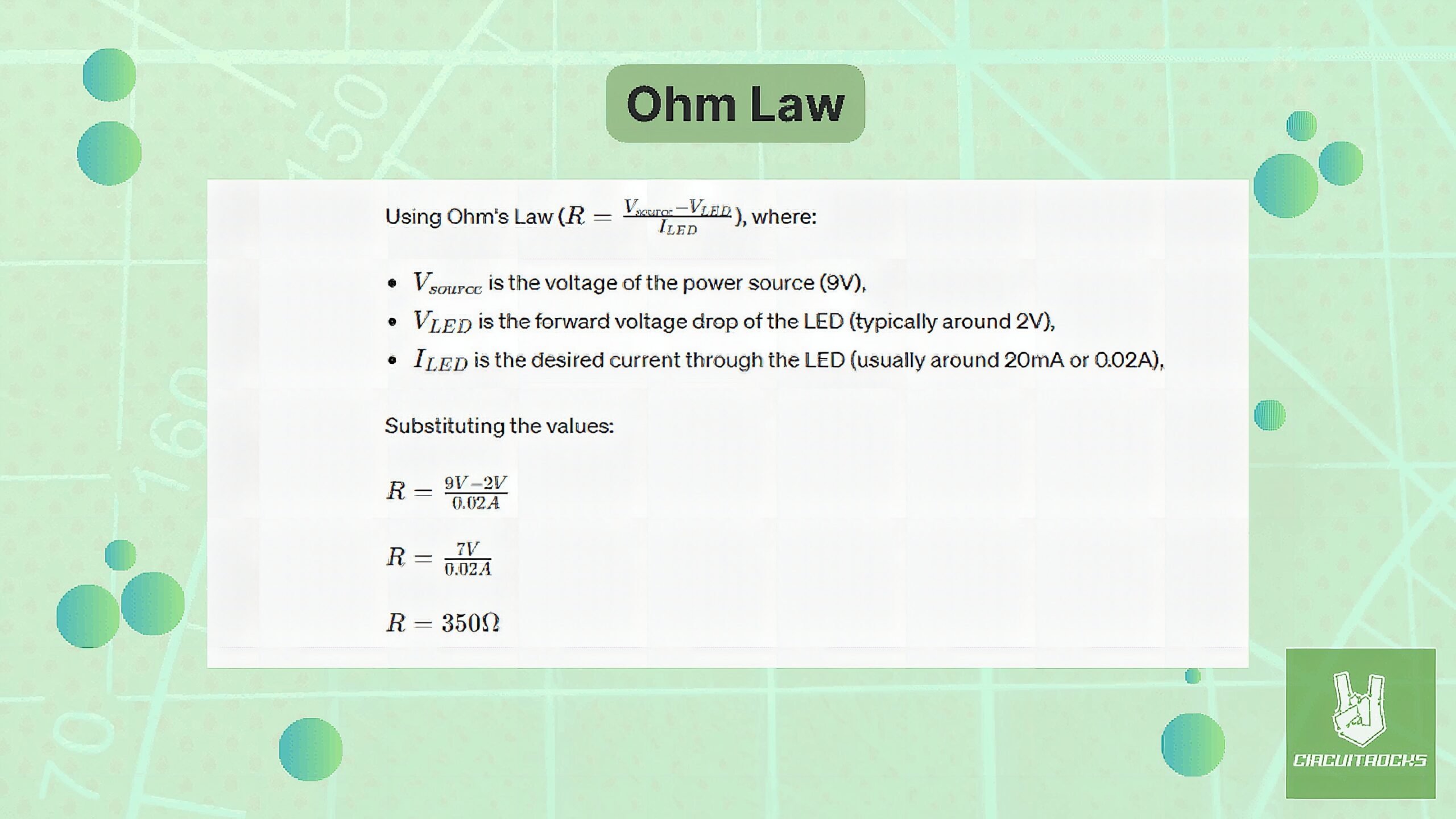
For this project, you will use 5 LEDs, 5 resistors, a 9V battery, and jumper wires. Each LED must have its own current-limiting resistor to prevent it from burning out. To figure out the right resistor value for each LED, you can use Ohm’s Law.
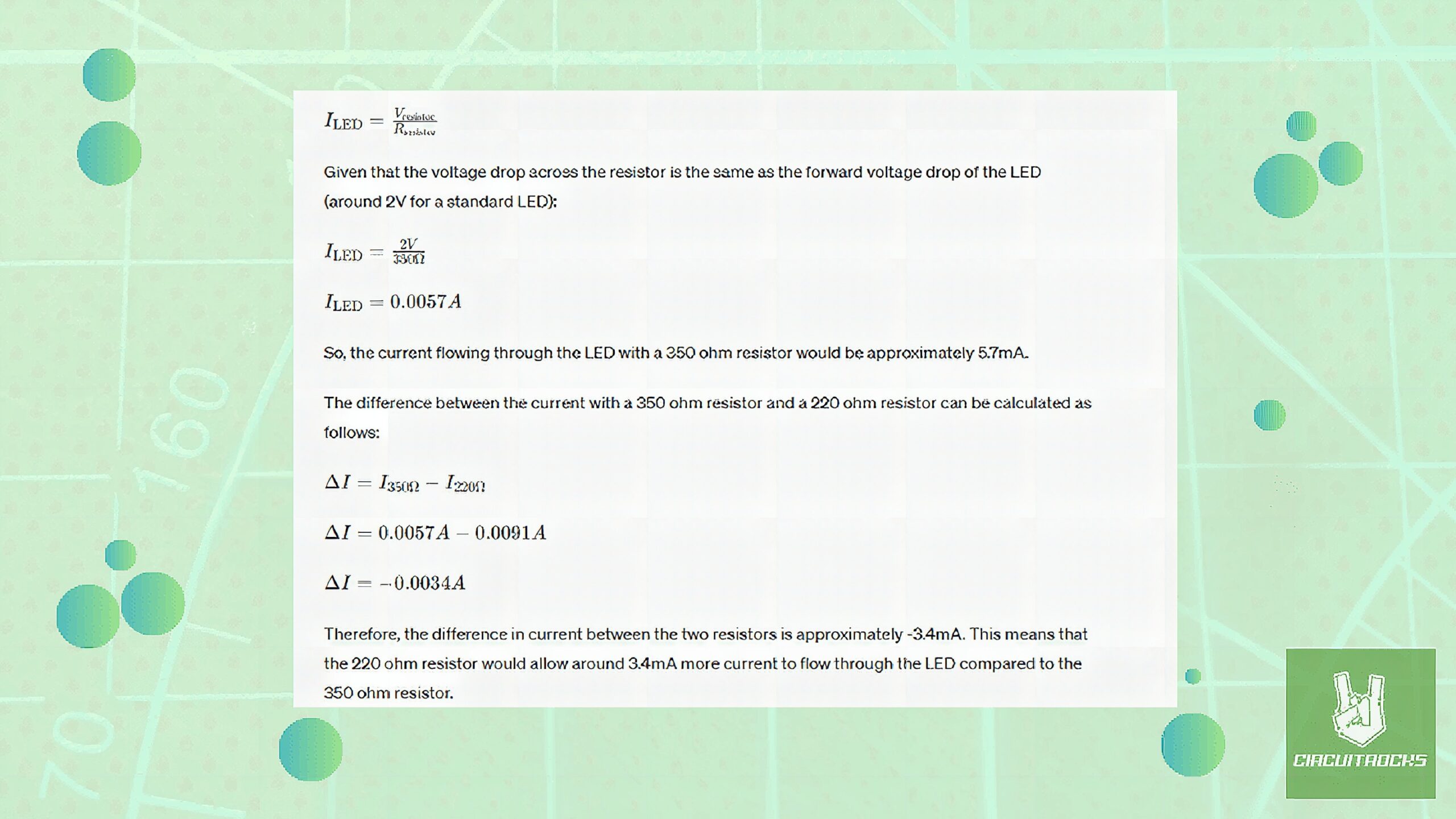
Using a 220 ohm resistor should be safe as long as they are typical rated for around 20mA current. The current (9.1mA) with a 220 ohm resistor compared to the calculated 350 ohm resistor (5.7mA) will make the LEDs slightly brighter, but it should not damage them.
Figuring out this circuit is the best way to understand. How parallel circuits work and the basic principles of current flow and component interaction. It teaches to build circuits, solder, identify and solve problems through first-hand practice, which nowadays are crucial skills of any aspiring electronics lover. Through gaining a good understanding of this very simple circuit. Students can start working on more advanced circuits with ease, providing them for further studying electronics.
Components
Remember
Soldering with lead-based solder gets easier with practice. Remember, safety first because lead is toxic. Always wash your hands after using lead-based solder and think about using lead-free solder if it works for your project.
QUICK LINK
Frequently Asked Questions
What does this Multi LED and Resistor in Parallel: A Quick Guide tutorial cover?
Learning how a parallel circuit works is an important first step in studying electronics.
What's the working voltage of the Multi LED and Resistor in Parallel: A Quick Guide?
Check the Sample Code section for the exact pinout — most maker-grade sensors run on 3.3V or 5V. Wire VCC to the matching rail, GND common with your MCU, data to a digital or analog pin.
Why does the Multi LED and Resistor in Parallel: A Quick Guide read garbage or saturated values?
Three usual causes: wrong voltage rail, missing pull-up resistor on I2C lines (4.7k–10k to VCC), or a floating data pin. Double-check wiring against the diagram, then probe with a multimeter.