
Knowing how to use a multimeter is one of the non-negotiables in starting electronics. In this tutorial, you will learn how to measure voltage, current resistance, and many more using the common digital multimeter.
Introduction
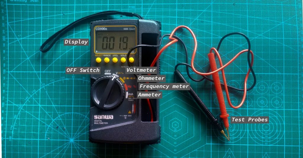
A multimeter, also known as multitester or VOM (Voltmeter-Ohmmeter-Milliammeter), is a measuring instrument that measures electrical quantities such as voltage, current, and resistance. It is used to test electronic components and troubleshoot electrical circuits like a short or open connection. The first generation of multimeters is limited to measuring voltage, current, and resistance only. These traditional multimeters are called Analog Multimeters. On the other hand, modern multimeters include autoranging, more intuitive display, data storage, and even a built-in oscilloscope. These are digital multimeters. We will discuss this further in the next section.
Analog or Digital Multimeter

Analog multimeters use the D-Arsonal movement to measure electricity. We won’t elaborate on how this mechanism works. All you need to know is that it does not need batteries to perform measurements. Analog multitesters are excellent for circuits that don’t require fast measurements or circuits with slow electrical changes. To read analog testers, you watch the needle moving over a scale. They are great in measuring current as they have lower resistance and higher sensitivity than their digital counterparts.
On the other hand, digital multimeters are meters that need batteries to operate. They are more commonly used as they offer convenience among its long list of advantages. Unlike analog testers, digital multimeters use LEDs or LCDs to show the measurement values. It also has automatic calibration, which makes it incredibly easier to measure unknown connections. Auto-ranging is exclusive to digital meters. It saves you the trouble of manually setting the range of voltage, current, and resistance values. In this tutorial, we will focus on digital multimeters rather than analog. However, the methods below can be used for analog testers as well.
Using the Multimeter for Measurement
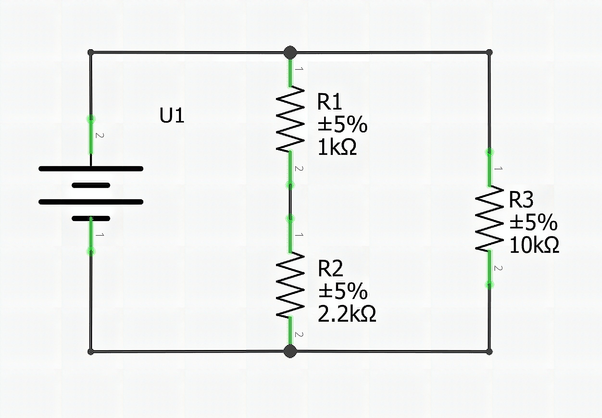
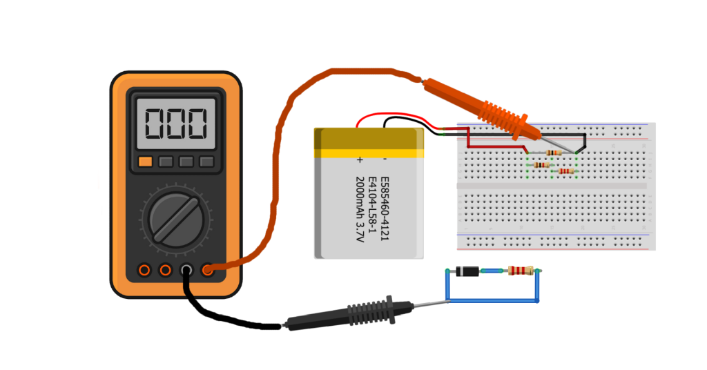
The main purpose of a multimeter is to measure electricity. In this section, we will measure voltage, current, and resistance values based on the circuit below.
Voltage

- First, if your multimeter has detachable probes, connect the probes to their corresponding slots – the black probe to the “COM” or common slot, the ground, and the red probe to the “V?” slot.
- Next, turn the knob to the DC Voltage sign. DC is often represented as a straight or a broken line. (Note: If the circuit runs on AC, you need to turn the knob to AC too). Other testers don’t have a separate place on the knob for AC and DC. You can change the voltage mode with a button instead. Check your manual for more details.
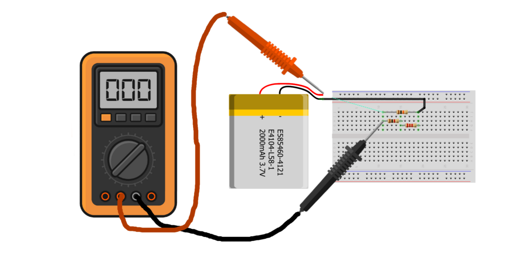
- Connect the red probe to the positive terminal of the part of the circuit you want to measure. In the case of our example, we measure the voltage level of the 1k? resistor. The probe must be on the positive side of the resistor as shown in Figure 3.
- Connect the black probe to the negative side of the resistor. In measuring voltage, the probes are always in parallel to the part of the circuit you want to measure.
- Read the results on the display.
Current
- First, if your multimeter has detachable probes, connect the probes to their corresponding slots – the black probe to the “COM” or common slot, the ground, and the red probe to the fused mA slot or the 10A slot. These slots are the usual design for digital multimeters. The mA slot supports only a range of current in milliamperes. If the measurement goes beyond that, the fuse will break to protect your tester. Now the slot won’t work unless you replace the broken fuse. For larger currents, use the 10A slot. It won’t be as accurate and precise as the mA slot but it is capable of measuring high rated currents.
- Next, turn the knob to the DC Voltage sign. DC is often represented as a straight or a broken line. (Note: If the circuit runs on AC, you need to turn the knob to AC too). Other testers don’t have a separate place on the knob for AC and DC. You can change the voltage mode with a button instead. Check your manual for more details.
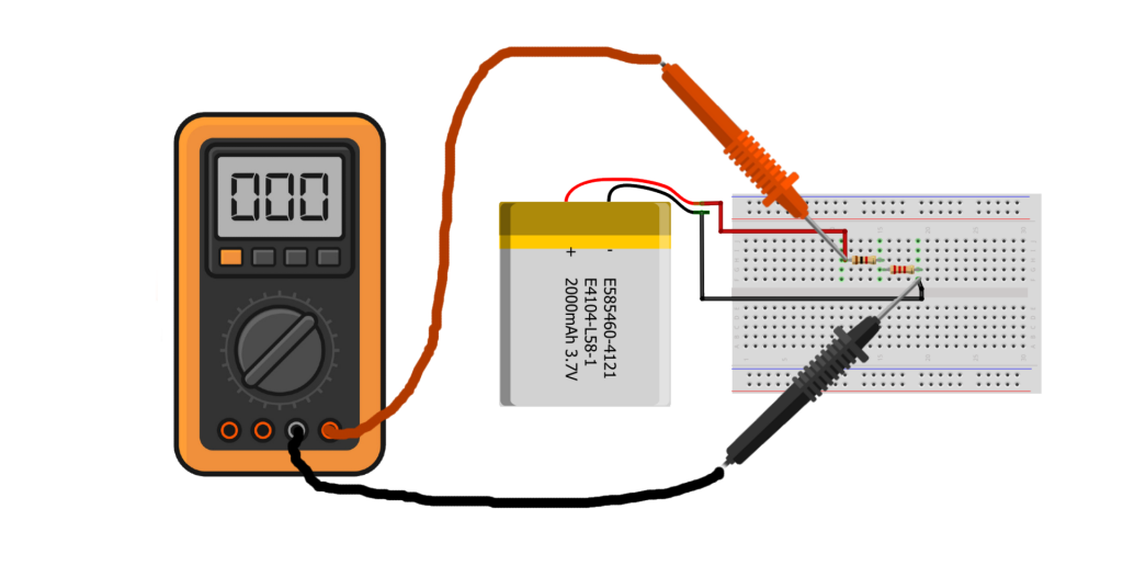
- Connect the red probe in series to the part of the circuit you want to measure. In the case of our example, we measure the current level of the entire circuit. The probe must be on the positive terminal of the battery as shown in Figure 4.
- Connect the black probe to the side where the positive terminal of the battery is supposed to connect. In measuring current, the probes are always in series to the part of the circuit you want to measure.
- Read the results on the display.
Resistance
- Connect the probes to their corresponding slots – the black probe to the “COM” or common slot, the ground, and the red probe to the “V?” slot.
- Touch the probes to the ends of the whole circuit to get the total resistance.
- Read the display on the screen.
Capacitance

- Turn the knob to capacitance testing mode – with the icon or symbol of a capacitor.
- Connect the probes to the capacitor ends.
- If polarized, determine the positive and negative sides.
- Read the result on the screen.
Continuity
Continuity is the presence of an unobstructed path for current flow. If there is no continuity, it means there is an open connection somewhere in the circuit. Digital multimeters often produce a sound to indicate continuity. I use this when soldering electronic components on a PCB (Printed Circuit Board). This way, I am sure everything onboard is properly connected. To check the continuity of a circuit, simply follow the steps below:
- Remove the power on your circuit.
- Connect the probes to their corresponding slots – the black probe to the “COM” or common slot, the ground, and the red probe to the “V?” slot.
- Turn the knob to continuity mode. This can also be done by pressing a button on your multimeter. Check your meter’s manual to be sure. The icon for continuity looks like sound waves.
- To test the continuity tester, touch the ends of the probes with each other. The multimeter should produce a sound as there is a complete path of current between the two probes.
- Place the probes at each end of the part of the circuit you want to test.
Using the Multimeter for Testing Semiconductors
Transistors
- Connect the probes to their corresponding slots – the black probe to the “COM” or common slot, the ground, and the red probe to the slot or terminal with the diode sign.
- Turn the knob to the diode tester.
- Connect alligator clamps to both metal end of the two probes.
- Determine which of the transistor leads is the collector, base, and emitter.
- Clamp the probes to the transistor leads – the black probe to the transistor base and the red probe to the emitter.
- Read the display on the multimeter and take note of the resistance.
- Remove the red probe from the emitter and move it to the collector side.
- The multimeter display should be the same as when the red probe was on the emitter side.
- Remove the black probe from the base side.
- Clamp the red probe to the base side.
- Clamp the black probe to the emitter side. Take note of the displayed value.
- Clamp the black probe to the collector side. Take note of the displayed value.
- If both previous readings (when the black probe is at the base) are higher than the current readings (when the red probe is at the base), the transistor is good.
- If both previous readings are lower than the current readings, the transistor is good.
- The transistor is bad if neither 13 or 14 is true.
Diodes
- Connect the probes to their corresponding slots – the black probe to the “COM” or common slot, which is the ground, and the red probe to the slot or terminal with the diode sign.
- Turn off the power source.
- Turn the knob to the diode tester.
- Determine the cathode and the anode of the diode. Touch the anode using the red probe and the cathode using the black probe.
- Read the display on the multimeter. If the reading is between 0.5 to 0.8V, then the diode is good. Otherwise, it’s not.
- Switch the black probe and the read probe.
- Read the display on the multimeter. If the reading is zero, then the diode is good. Otherwise, it’s not.
Frequently Asked Questions
What does this How to Use a Multimeter tutorial cover?
Knowing how to use a multimeter is one of the non-negotiables in starting electronics.
What's the working voltage of the How to Use a Multimeter?
Check the Sample Code section for the exact pinout — most maker-grade sensors run on 3.3V or 5V. Wire VCC to the matching rail, GND common with your MCU, data to a digital or analog pin.
Why does the How to Use a Multimeter read garbage or saturated values?
Three usual causes: wrong voltage rail, missing pull-up resistor on I2C lines (4.7k–10k to VCC), or a floating data pin. Double-check wiring against the diagram, then probe with a multimeter.