
The Problem
My SIM800L v2 module had its network LED blinking every second, but it never picked up a signal. I powered it off a laptop USB port, then off a 5V/2A charger adapter. No change. Swapped the SIM card too. Still nothing.
What I Tried First
I went back over the wiring diagram and double-checked every connection. Nothing wrong there. So I added a DC-DC converter to give it a cleaner voltage supply and put capacitors on both sides. The LED kept blinking anyway.
Root Cause: Wire Length
After poking at this for way too long, I found it. The breadboard and jumper wires were the problem. They were long enough to choke the current getting to the SIM800L.
The Fix
Once I knew that, the fix was easy. I cut the breadboard and jumper wires way down, around 2-3cm, so more current could actually reach the module. Then I dropped a capacitor right next to it, between Vcc and GND. That did it. The trouble showed up mostly after entering the SIM pin, when the module pulls a burst of current and the voltage sags. Shorter wires plus the local cap kept the voltage from dropping, and the blinking stopped.
So the whole thing came down to the wiring, not the code or the module. If your SIM800L keeps blinking and won’t register, check your breadboard and jumper wires before you tear anything else apart. On a module that draws current in bursts like this one, a few centimeters of wire can be the difference between working and not.
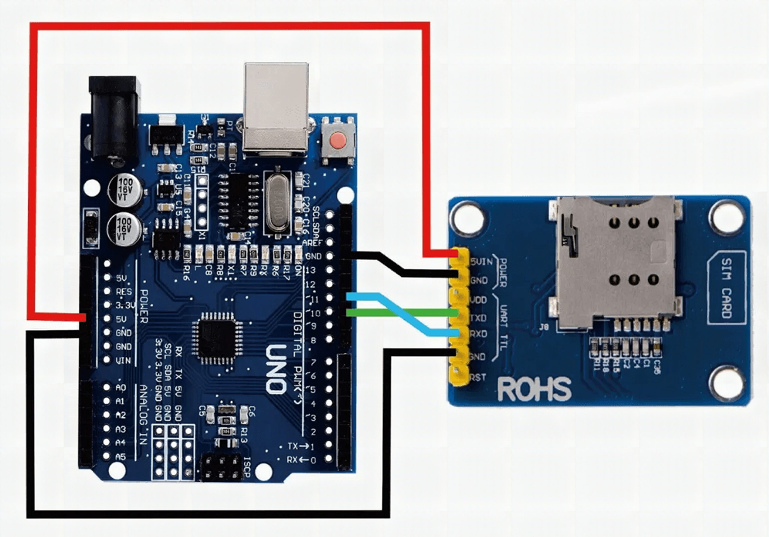
Test Code
Code:
SoftwareSerial sim(10, 11);
int _timeout;
String _buffer;
String number = "+6281222329xxx"; //-> change with your number void setup() { //delay(7000); //delay for 7 seconds to make sure the modules get the signal Serial.begin(9600); _buffer.reserve(50); Serial.println("Sistem Started..."); sim.begin(9600); delay(1000); Serial.println("Type s to send an SMS, r to receive an SMS, and c to make a call");
} void loop() { if (Serial.available() > 0) switch (Serial.read()) { case 's': SendMessage(); break; case 'r': RecieveMessage(); break; case 'c': callNumber(); break; } if (sim.available() > 0) Serial.write(sim.read());
} void SendMessage() { //Serial.println ("Sending Message"); sim.println("AT+CMGF=1"); //Sets the GSM Module in Text Mode delay(200); //Serial.println ("Set SMS Number"); sim.println("AT+CMGS="" + number + ""r"); //Mobile phone number to send message delay(200); String SMS = "Hello, how are you? greetings from miliohm.com admin"; sim.println(SMS); delay(100); sim.println((char)26);// ASCII code of CTRL+Z delay(200); _buffer = _readSerial();
} void RecieveMessage() { Serial.println ("SIM800L Read an SMS"); sim.println("AT+CMGF=1"); delay(200); sim.println("AT+CNMI=1,2,0,0,0"); // AT Command to receive a live SMS delay(200); Serial.write ("Unread Message done");
} String _readSerial() { _timeout = 0; while (!sim.available() && _timeout < 12000) { delay(13); _timeout++; } if (sim.available()) { return sim.readString(); }
} void callNumber() { sim.print (F("ATD")); sim.print (number); sim.print (F(";rn")); _buffer = _readSerial(); Serial.println(_buffer);
}Frequently Asked Questions
What does this SIM800l V2 Keeps Blinking Every Second tutorial cover?
With my SIM800L v2 module, I was in a dilemma because the network LED kept blinking every second; however, it did not receive any signal whatsoever.
What's the working voltage of the SIM800l V2 Keeps Blinking Every Second?
Check the Sample Code section for the exact pinout — most maker-grade sensors run on 3.3V or 5V. Wire VCC to the matching rail, GND common with your MCU, data to a digital or analog pin.
Why does the SIM800l V2 Keeps Blinking Every Second read garbage or saturated values?
Three usual causes: wrong voltage rail, missing pull-up resistor on I2C lines (4.7k–10k to VCC), or a floating data pin. Double-check wiring against the diagram, then probe with a multimeter.
