
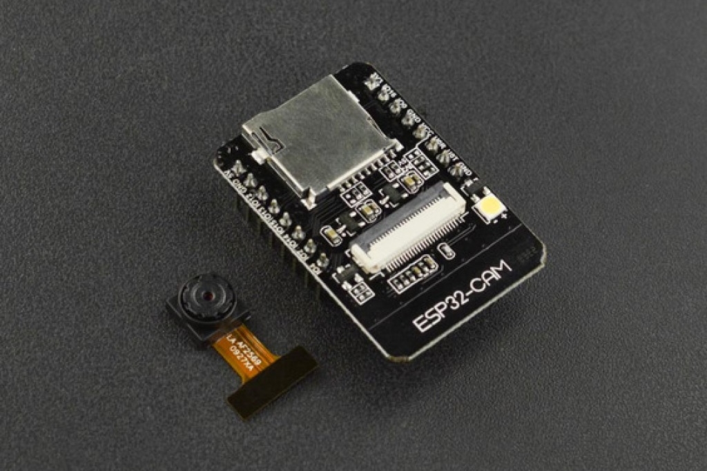
The ESP32-CAM is one of the cheapest solutions if you want to add video recording to your IoT project. In this tutorial, you will learn the following:
- how to program the ESP32-CAM
- how to do browser-based and RTSP video streaming
- how to use an FTDI adapter to program the ESP32-CAM
- how to use OTA to program the ESP32-CAM over WiFi
Before you start
The ESP32-CAM development board is different from other ESP32 breakout boards because there is no USB connector. So programming the board is different from what you know. You will need a FTDI USB to Serial converter like this one to see the Serial debug output and program the ESP32.
You will need in addition a button to put the ESP32-CAM into download mode.
The ESP32-CAM board is power hungry! You need at least a 2A 5V power supply or the board will not boot up. This one with a 2A output is a good choice.
The camera in action.
Credentials
The code provided here is based on Kevin Hestners Micro-RTSP example code. You can find the library and original example code on his Github repo.
For the button functions the OneButton library provided by Matthias Hertel is used.
Sources
Source code on Github https://github.com/circuitrocks/ESP32-RTSP
OneButton library https://github.com/mathertel/OneButton
Micro-RTSP sources https://github.com/geeksville/Micro-RTSP
ESP32-CAM https://circuit.rocks/product:2659
Camera case as Fusion360 file https://github.com/circuitrocks/ESP32-RTSP/blob/master/3D/ESP32-CAM-Case.f3z
Camera case STL files for 3D printing https://github.com/circuitrocks/ESP32-RTSP/tree/master/3D
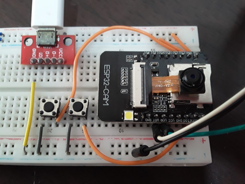
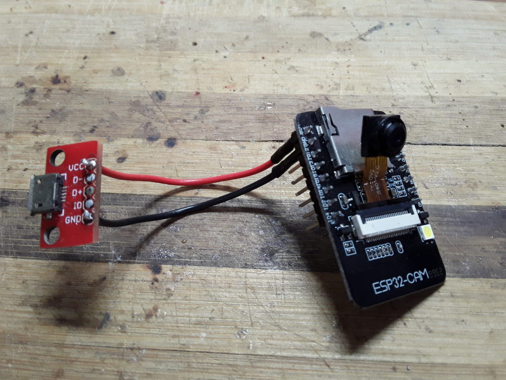
Step 1: Hook up the ESP32-CAM board for testing
As said before, programming the ESP32-CAM is different to other EPS32 breakouts.
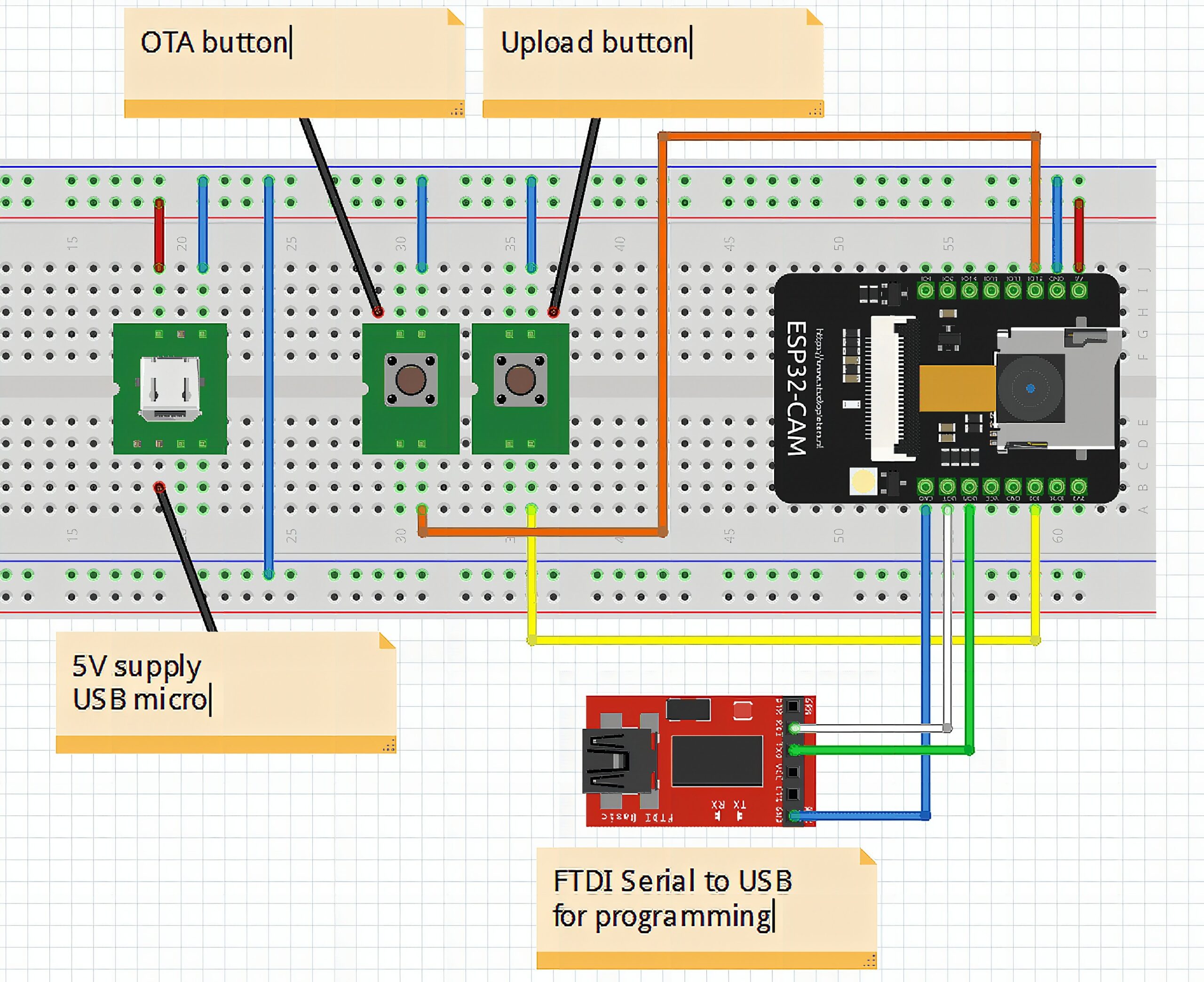
First thing is the power supply. You need to apply 5V directly to the header pins 5V and GND.
Second thing is the programming adapter. TXD, RXD and GND of your FTDI adapter will be connected to the header pins UOT (RXD), UOR (TXD) and GND.
Third thing is the button to put the ESP32 into programming mode. This button needs to be connected to IO0 and GND. During normal function the IO0 is used as one of the control pins to the camera. The wire on IO0 must be as short as possible, because some of the ESP32-CAM boards are very sensitive on noise on this pin.
Here is the Fritzing schematic for easy understanding:
Step 2: Test if you can force the ESP32 into download mode
To bring the ESP32 into programming mode you need to push the DOWNLOAD button (the right side on in the Fritzing sketch) and keep it pushed while you power up or reset the ESP32-CAM board. The reset button is on the opposite side of the board, so a little bit difficult to reach.
If it works and your FTDI wires are correct, you will see in the serial monitor the following output:
ets Jun 8 2016 00:22:57 rst:0x1 (POWERON_RESET),boot:0x3 (DOWNLOAD_BOOT(UART0/UART1/SDIO_REI_REO_V2))
waiting for download
If you see nothing in the serial monitor, or a message that doesn’t say “DOWNLOAD_BOOT” and “waiting for download“, check your FTDI wiring and the connections of the DOWNLOAD button.
Step 3: Prepare your development environment
First get the source code from our Github repo as ZIP file and uncompress the content to your harddisk.
PlatformIO
On PlatformIO it is quite simple, because all you need to do is to download the complete repository from our Github and open the folder in PlatformIO. All required libraries will be automatically added when you start compiling the source code.
To choose if you want to flash the ESP32-CAM over USB or over OTA, comment/uncomment one of the two upload_port entries.
; upload_port = COM3
upload_port = 192.168.0.109
ArduinoIDE
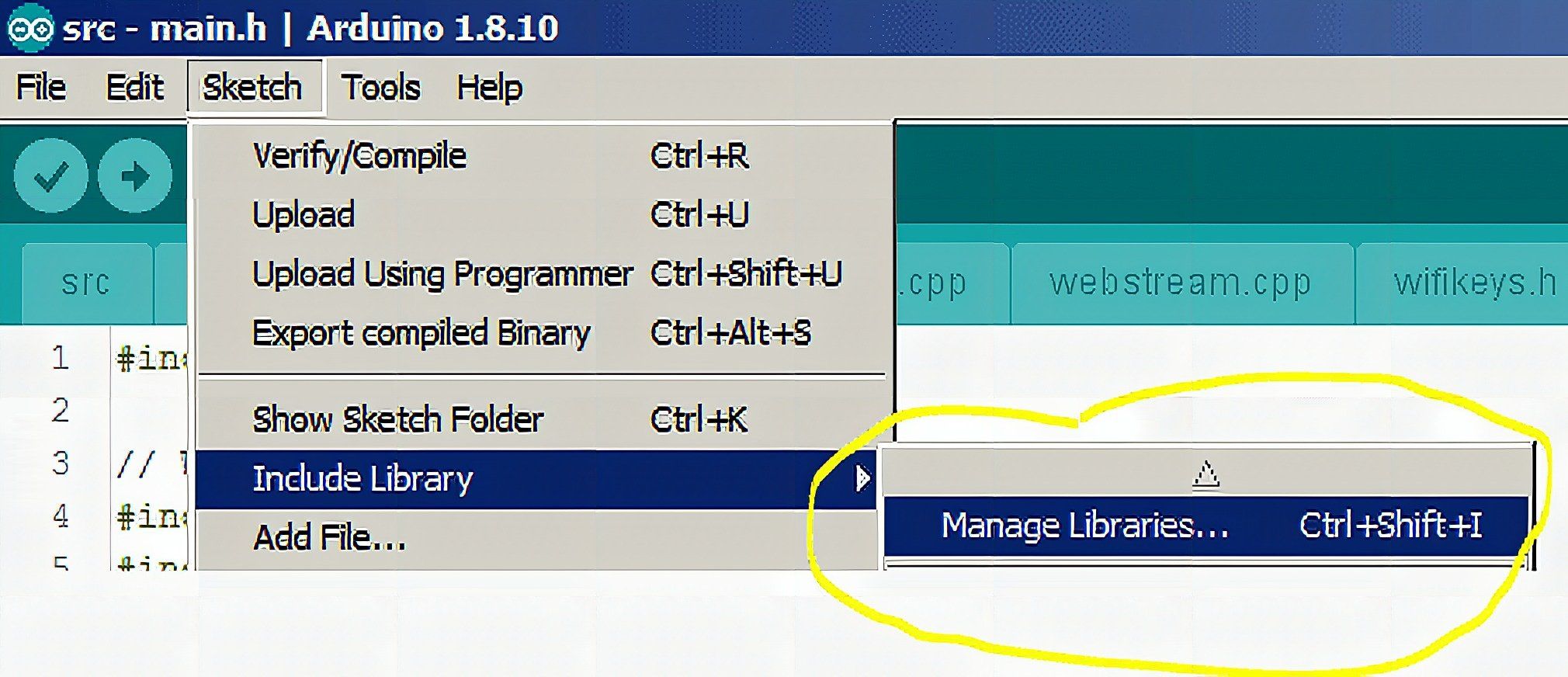
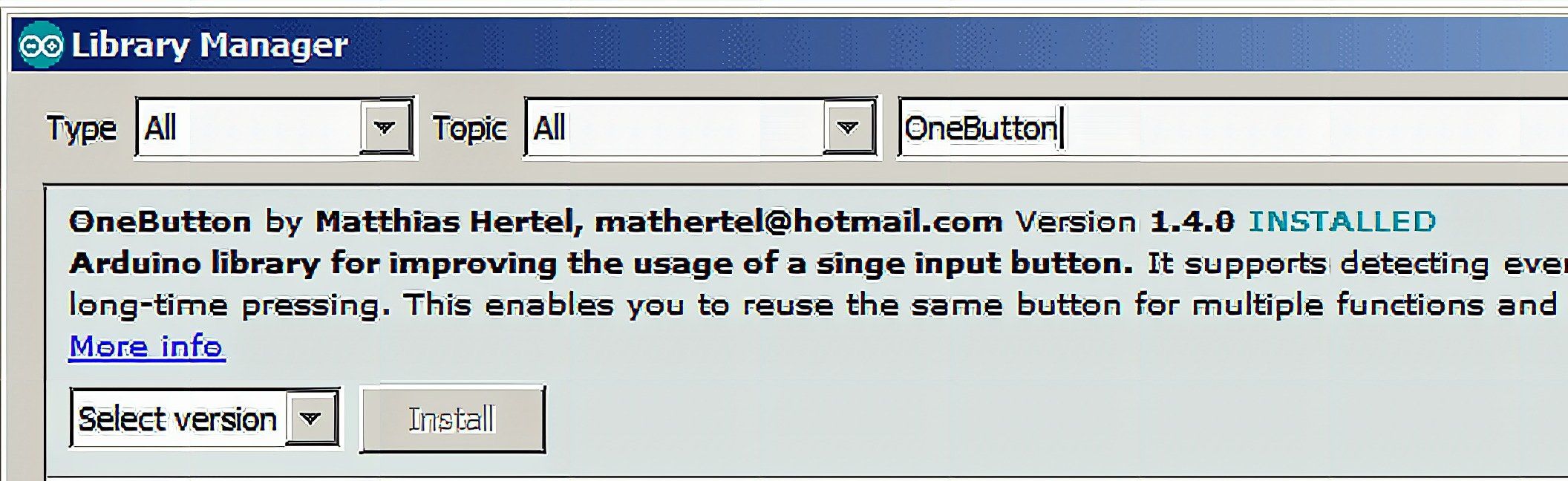
To compile the code with ArduinoIDE you need to install two libraries. The first one, OneButton is available with the build in library manager. Open the library manager and search for OneButton. If not installed yet, install it.
The second library, Micro-RTSP, is a little bit more complicated, because it is not available through the library manager.
We included the library as a ZIP file in our Github repository. When you download the source codes, you will find the library in the ArduinoIDE subfolder.
In ArduinoIDE go to Sketch -> Include Library -> Add.ZIP Library…
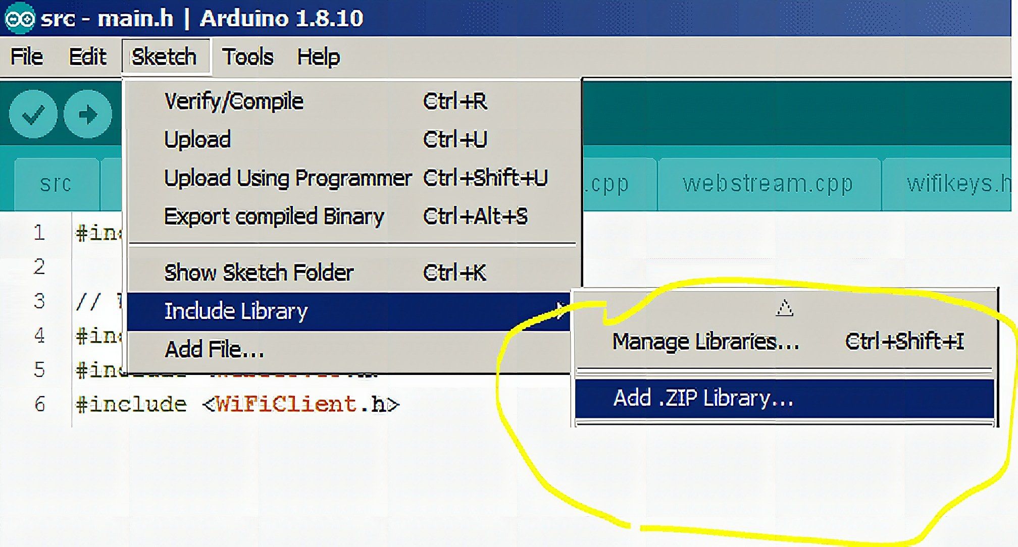
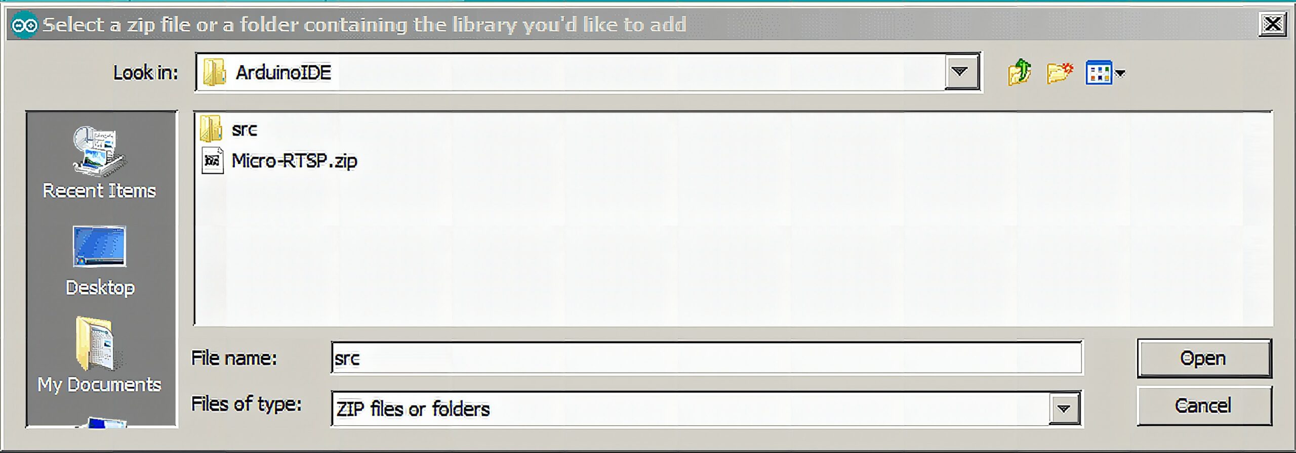
Then navigate to the ESP32-RTSP source code folder, then to ArduinoIDE and select the Micro-RTSP.zip file
After successfull installing both libraries, the sketch is now ready for compilation.
Open the src.ino file with ArduinoIDE. Don’t be surprised that the file is empty. It is here only for compatibility with ArduinoIDE. The real sources are in the .cpp and .h files in the same folder.
Setup your WiFi credentials
Before starting to compile the code, edit the file wifikeys.h and enter your WiFi credentials there.
#include <Arduino.h>
// Change YOUR_AP_NAME and YOUR_AP_PASSWORD to your WiFi credentials
const char *ssid = "YOUR_AP_NAME"; // Put your SSID here
const char *password = "YOUR_AP_PASSWORD"; // Put your PASSWORD here
Next: OTA (Over The Air) updates
As you could see above, it is a little bit of effort to flash the ESP32-CAM over USB, so the first thing I did add to the software is to enable OTA updates. That makes it easy to update the module without the need of a wired connection.
For implementing OTA we need 3 includes in the main.h include file
// OTA stuff
#include <ESPmDNS.h>
#include <WiFiUdp.h>
#include <ArduinoOTA.h>
UDP is the network protocol used for the update, mDNS is to advertise the name of the device over the network and ArduinoOTA is the library for OTA.
To initialize and start the OTA service I wrote the function startOTA. ArduinoOTA has callbacks, which informs the main app about the start, the end, the progress and errors that occur. These callbacks are defined in the ota.cpp file.
/** * Initialize OTA server * and start waiting for OTA requests */
void startOTA(void)
{ ArduinoOTA // OTA request received.onStart([]() { String type; if (ArduinoOTA.getCommand() == U_FLASH) type = "sketch"; else // U_SPIFFS type = "filesystem"; // NOTE: if updating SPIFFS this would be the place to unmount SPIFFS using SPIFFS.end() Serial.println("Start updating " + type); lastProgress = 0; otaStarted = true; }).onEnd([]() { // OTA is finished Serial.println("nEnd"); }).onProgress([](unsigned int progress, unsigned int total) { // Status report during OTA if ((lastProgress == 0) || ((progress / (total / 100)) >= lastProgress + 5)) { Serial.printf("Progress: %u%%r", (progress / (total / 100))); lastProgress = (progress / (total / 100)); if (lastProgress == 0) { lastProgress = 1; } } }).onError([](ota_error_t error) { // Error occured during OTA, report it Serial.printf("Error[%u]: ", error); if (error == OTA_AUTH_ERROR) Serial.println("Auth Failed"); else if (error == OTA_BEGIN_ERROR) Serial.println("Begin Failed"); else if (error == OTA_CONNECT_ERROR) Serial.println("Connect Failed"); else if (error == OTA_RECEIVE_ERROR) Serial.println("Receive Failed"); else if (error == OTA_END_ERROR) Serial.println("End Failed"); }); // Enable MDNS so device can be seen ArduinoOTA.setMdnsEnabled(false); // Create a unique name IPAddress ip = WiFi.localIP(); String hostName = "ESP32-CAM-" + ip.toString(); Serial.printf("Device is advertising as %sn", hostName.c_str()); // Set the MDNS advertising name ArduinoOTA.setHostname(hostName.c_str()); // Start the OTA server ArduinoOTA.begin();
}
To stop the OTA service a very simple subroutine is needed
/** * Stop the OTA server */
void stopOTA(void)
{ ArduinoOTA.end();
}
The call ArduinoOTA.end() will stop the service that is listening to OTA requests.
To handle OTA requests in the loop() function you just call
ArduinoOTA.handle();to check the service.
Usually you would start the OTA service from the setup() function and just let it run in the background. But while testing the app, I found that the OTA service is interfering with the UDP streaming of the video. So I decided to start the OTA service only when the user requests it by pushing a button.
So instead of calling ArduinoOTA.handle() all the time from the loop() function, I added an additional button. Pushing the button once stops the RTSP and web streaming servers and starts the OTA server. Pushing the button a second time, stops the OTA server and restarts the streaming servers.
In addition I added the option to restart the device by a fast double click on the button.
All of these functions are very easy to do with the OneButton library.
// Button stuff
#include <OneButton.h>
This is the only include required. Then the button is defined with
/** GPIO for OTA request button */
int otaButton = 12;
/** Button class */
OneButton pushBt(otaButton, true, true);
and two functions are attached as single and double click
// Attach the button functions
pushBt.attachClick(enableOTA);
pushBt.attachDoubleClick(resetDevice);
And in the main loop() we add
// Check the button
pushBt.tick();
to handle button events.
I really love the OneButton library, because it does
- debounce the button clicks in the background
- has an options for single, double click and long-press
In the enableOTA function we simple check whether the OTA server is active right now or not and switch on/off the servers accordingly
/** * Handle button single click */
void enableOTA(void)
{ // If OTA is not enabled if (!otaStarted) { // Stop the camera servers
#ifdef ENABLE_WEBSERVER stopWebStream();
#endif
#ifdef ENABLE_RTSPSERVER stopRTSP();
#endif delay(100); Serial.println("OTA enabled"); // Start the OTA server startOTA(); otaStarted = true; } else { // If OTA was enabled otaStarted = false; // Stop the OTA server stopOTA(); // Restart the camera servers
#ifdef ENABLE_WEBSERVER initWebStream();
#endif
#ifdef ENABLE_RTSPSERVER initRTSP();
#endif }
}
And in the second function we initiate a SW reset of the ESP32
/** * Handle button double click */
void resetDevice(void)
{ delay(100); WiFi.disconnect(); esp_restart();
}
Finally: The streaming functions.
The app has two video streaming options:
- Streaming directly to a web browser
- Streaming as an RTSP server (See Wikipedia for an explanation of RTSP)
To select one of the two servers open main.h and enable the server you want to run
// Select which of the servers are active
// Select only one or the streaming will be very slow!
#define ENABLE_WEBSERVER
#define ENABLE_RTSPSERVER
Only one of the servers should be enabled. If you enable both servers, the streaming will be very slow.
Streaming to a web browser
This is a quite simple way to stream a video from a WiFi camera. Basically the ESP32 starts a web server and on connection by a web browser sends images from the camera to the web browser. So it is not a real data stream from the camera, but more like a stream of images.
To enable the web browser streaming we use the web server from the Arduino ESP32 framework.
/** Web server class */
WebServer server(80);
initializes the web server to serve incoming HTTP requests on port 80.
// Set the function to handle stream requests server.on("/", HTTP_GET, handle_jpg_stream); // Set the function to handle single picture requests server.on("/jpg", HTTP_GET, handle_jpg); // Set the function to handle other requests server.onNotFound(handleNotFound);defines the actions on different HTTP requests.
A simple http://<IP-ADDRESS>/ request starts the continuous streaming of images to the web browser.
http://<IP-ADDRESS>/jpg sends a single image from the camera to the web browser
And all other requests are ignored.
Then the web server is started
// Start the web server
server.begin();
And with
// Check if the server has clients
server.handleClient();
we handle the requests.
For the continuous streaming of images the subroutine handle_jpg_stream() is doing two things. #1 it informs the web browser of the data it will send. And #2 it sends images from the camera in a loop until the web browser disconnects.
/** * Handle web stream requests * Gives a first response to prepare the streaming * Then runs in a loop to update the web content * every time a new frame is available */
void handle_jpg_stream(void)
{ WiFiClient thisClient = server.client(); String response = "HTTP/1.1 200 OKrn"; response += "Content-Type: multipart/x-mixed-replace; boundary=framernrn"; server.sendContent(response); while (1) { cam.run(); if (!thisClient.connected()) { break; } response = "--framern"; response += "Content-Type: image/jpegrnrn"; server.sendContent(response); thisClient.write((char *)cam.getfb(), cam.getSize()); server.sendContent("rn"); delay(150); }
}
Single image requests are handled by the handle_jpg() subroutine. It reads a picture from the camera and sends it to the web browser.
/** * Handle single picture requests * Gets the latest picture from the camera * and sends it to the web client */
void handle_jpg(void)
{ WiFiClient thisClient = server.client(); cam.run(); if (!thisClient.connected()) { return; } String response = "HTTP/1.1 200 OKrn"; response += "Content-disposition: inline; filename=capture.jpgrn"; response += "Content-type: image/jpegrnrn"; server.sendContent(response); thisClient.write((char *)cam.getfb(), cam.getSize());
}
And for all other requests the function handleNotFound just sends a simple response with instructions back to the web browser
/** * Handle any other request from the web client */ void handleNotFound()
{ IPAddress ip = WiFi.localIP(); String message = "Stream Link: rtsp://"; message += ip.toString(); message += ":8554/mjpeg/1n"; message += "Browser Stream Link: http://"; message += ip.toString(); message += "n"; message += "Browser Single Picture Link: http//"; message += ip.toString(); message += "/jpgn"; message += "n"; server.send(200, "text/plain", message);
}
As an approach to have both web streaming and RTSP streaming running in parallel I run them in independent FreeRTOS tasks. The web streaming task is started with a call to
/** * Initialize the web stream server by starting the handler task */
void initWebStream(void)
{
#ifdef ENABLE_WEBSERVER
// Create the task for the web server xTaskCreate(webTask, "WEB", 4096, NULL, 1, &webTaskHandler); if (webTaskHandler == NULL) { Serial.println("Create Webstream task failed"); } else { Serial.println("Webstream task up and running"); }
#endif
}
In the newly started task we do then the setup and start of the web server and handle in an endless loop the incoming http requests. The task is stopped by the flag stopWeb which can be set from the main loop() in case we want to activate the OTA server.
/** * The task that handles web server connections * Starts the web server * Handles requests in an endless loop * until a stop request is received because OTA * starts */
void webTask(void *pvParameters)
{ // Set the function to handle stream requests server.on("/", HTTP_GET, handle_jpg_stream); // Set the function to handle single picture requests server.on("/jpg", HTTP_GET, handle_jpg); // Set the function to handle other requests server.onNotFound(handleNotFound); // Start the web server server.begin(); while (1) {
#ifdef ENABLE_WEBSERVER // Check if the server has clients server.handleClient();
#endif if (stopWeb) { // User requested web server stop server.close(); // Delete this task vTaskDelete(NULL); } delay(100); }
}
Watch the jpeg stream in a browser
To watch the camera stream on a web browser use the urls
Browser Stream Link: http://192.168.0.109
Browser Single Picture Link: http//192.168.0.109/jpg
to see either a continous stream of images or a single snapshot.
Replace the IP address in the URL with the IP address of your ESp32-CAM board.
The RTSP server
The RTSP server used is the Micro-RTSP server library from Kevin Hestner. To run it beside of a server a streamer (for streaming the video) and a session (to handle the RTP communication) is required. The wifi client is the handle for the connected RTSP client.
/** WiFi server for RTSP */
WiFiServer rtspServer(8554); /** Stream for the camera video */
CStreamer *streamer = NULL;
/** Session to handle the RTSP communication */
CRtspSession *session = NULL;
/** Client to handle the RTSP connection */
WiFiClient rtspClient;
Same as for the web streaming server we use an independent FreeRTOS task to handle requests. The task is started with a call to initRTSP()
/** * Starts the task that handles RTSP streaming */
void initRTSP(void)
{ // Create the task for the RTSP server xTaskCreate(rtspTask, "RTSP", 4096, NULL, 1, &rtspTaskHandler); // Check the results if (rtspTaskHandler == NULL) { Serial.println("Create RTSP task failed"); } else { Serial.println("RTSP task up and running"); }
}
Inside the task, we initialize the RTSP server and start it. After that we handle in an endless loop incoming requests. And in case that the OTA server is started, the server and the task can be stopped by the flag stopRTSPtask
/** * The task that handles RTSP connections * Starts the RTSP server * Handles requests in an endless loop * until a stop request is received because OTA * starts */
void rtspTask(void *pvParameters)
{ uint32_t msecPerFrame = 200; static uint32_t lastimage = millis(); // rtspServer.setNoDelay(true); rtspServer.setTimeout(1); rtspServer.begin(); while (1) { // If we have an active client connection, just service that until gone if (session) { session->handleRequests(0); // we don't use a timeout here, // instead we send only if we have new enough frames uint32_t now = millis(); if (now > lastimage + msecPerFrame || now < lastimage) { // handle clock rollover session->broadcastCurrentFrame(now); lastimage = now; // check if we are overrunning our max frame rate now = millis(); if (now > lastimage + msecPerFrame) printf("warning exceeding max frame rate of %d msn", now - lastimage); } // Handle disconnection from RTSP client if (session->m_stopped) { Serial.println("RTSP client closed connection"); delete session; delete streamer; session = NULL; streamer = NULL; } } else { rtspClient = rtspServer.accept(); // Handle connection request from RTSP client if (rtspClient) { Serial.println("RTSP client started connection"); streamer = new OV2640Streamer(&rtspClient, cam); // our streamer for UDP/TCP based RTP transport session = new CRtspSession(&rtspClient, streamer); // our threads RTSP session and state delay(100); } } if (stopRTSPtask) { // User requested RTSP server stop if (rtspClient) { Serial.println("Shut down RTSP server because OTA starts"); delete session; delete streamer; session = NULL; streamer = NULL; } // Delete this task vTaskDelete(NULL); } delay(10); }
}
Inside the endless loop you can see that we initate the streaming of a image frame every 200 ms (defined by uint32_t msecPerFrame = 200;). The time between sending two frames defines how smooth the video is shown in the RTSP client. How fast you can go depends basically on what your local WiFi network (and the ESP32 processing power) can handle. For my environment the 200ms was good value.
How to watch the RTSP stream.
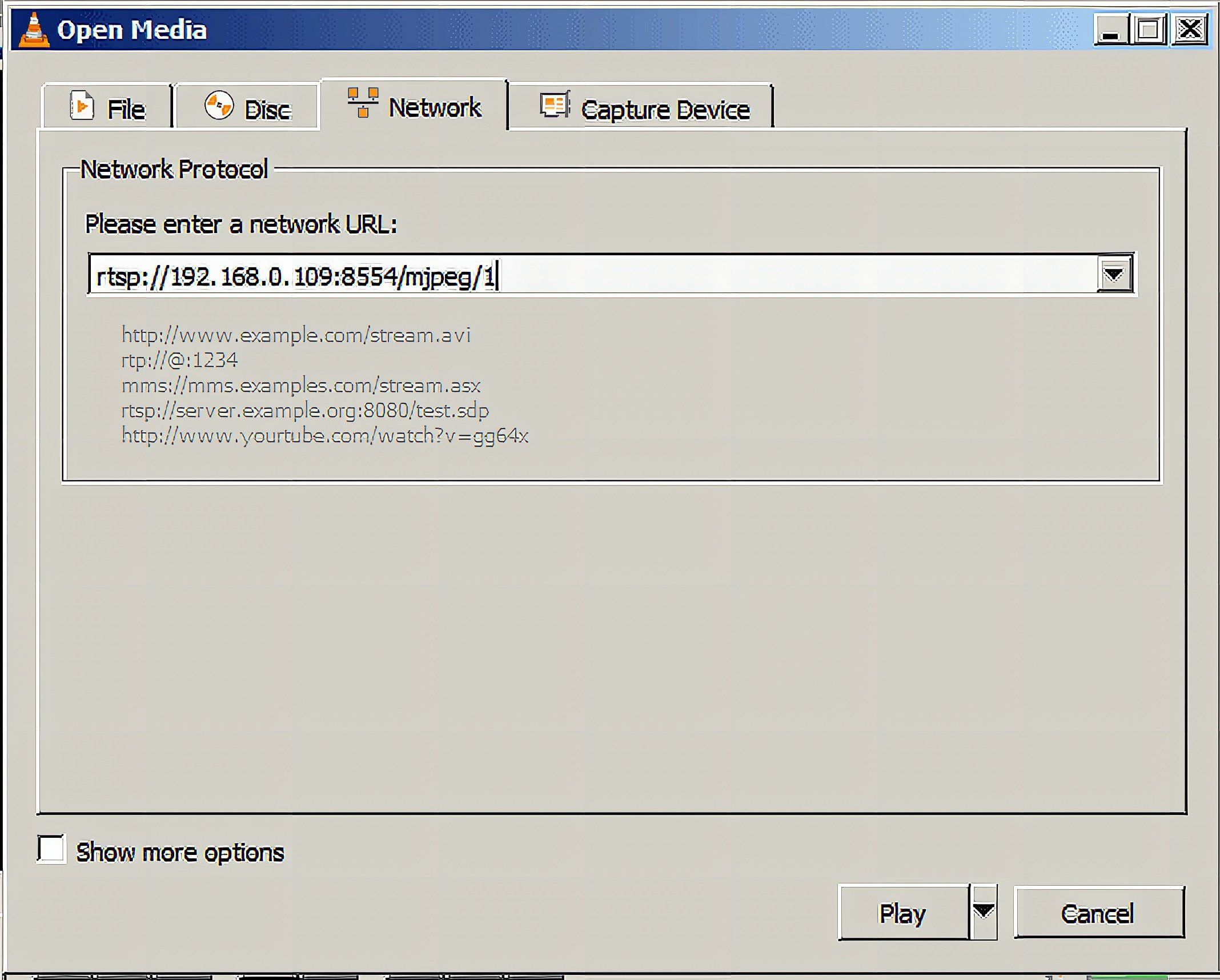
To receive the RTSP stream and watch it there are several options. For all options you need to setup the RTSP network address as
rtsp://192.168.0.109:8554/mjpeg/1
and replace the IP address with the one that your ESP32 uses.
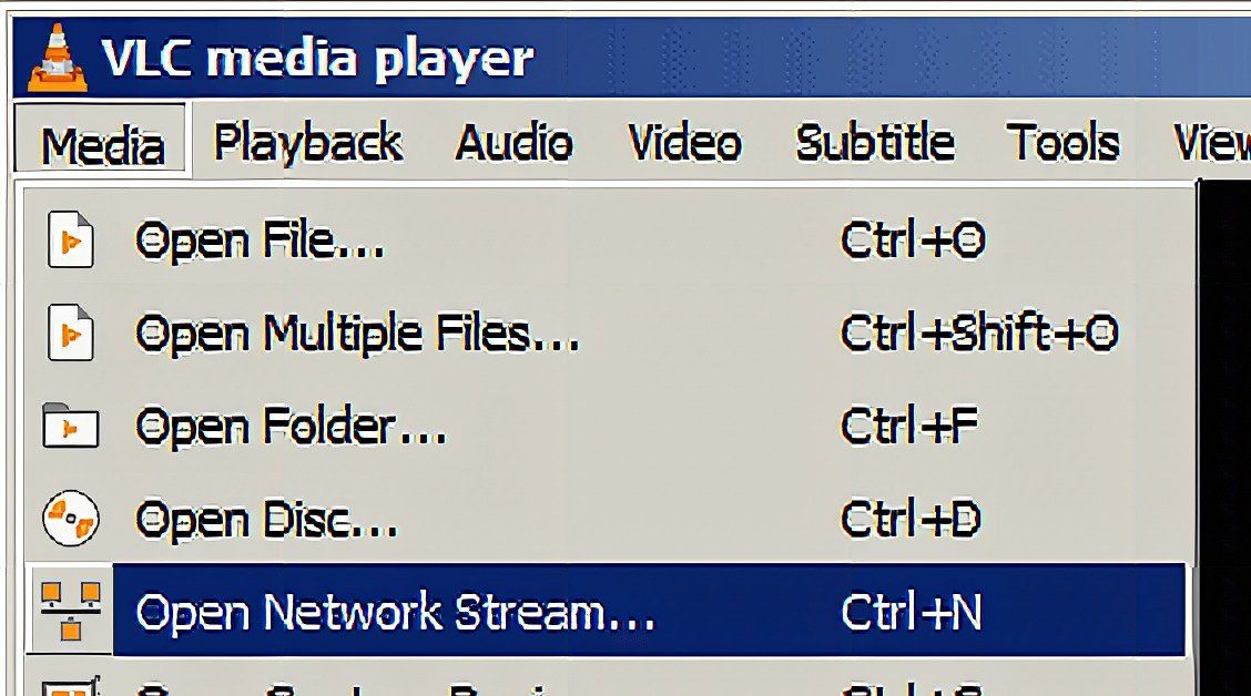
On a Windows PC you can use e.g. VLC and connect to the network
On an Android device you can use VLC as well. Or any other of the many RTSP clients available.
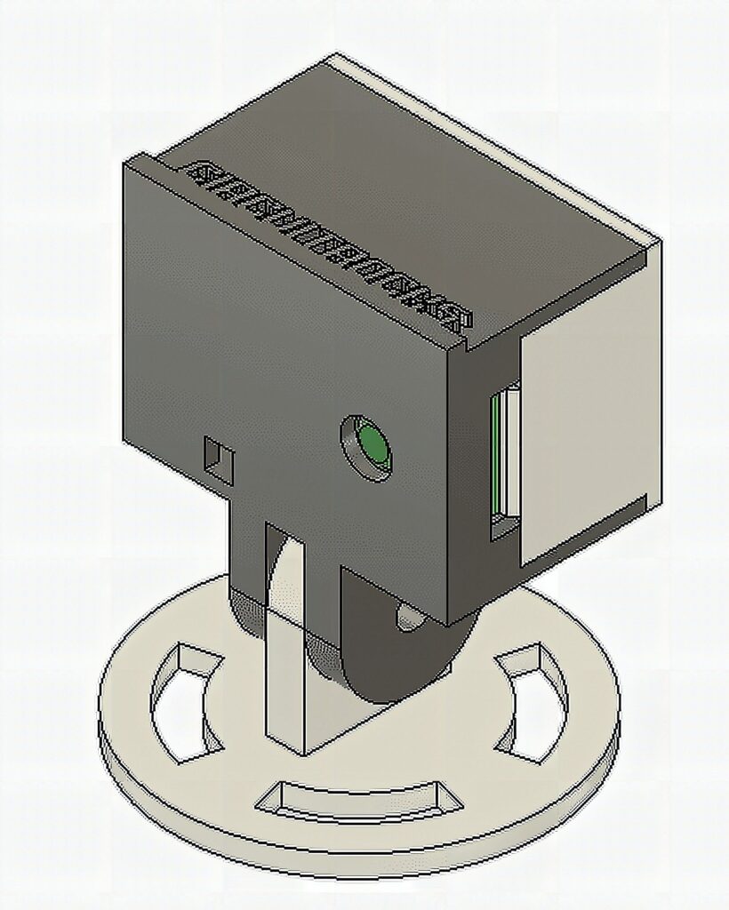
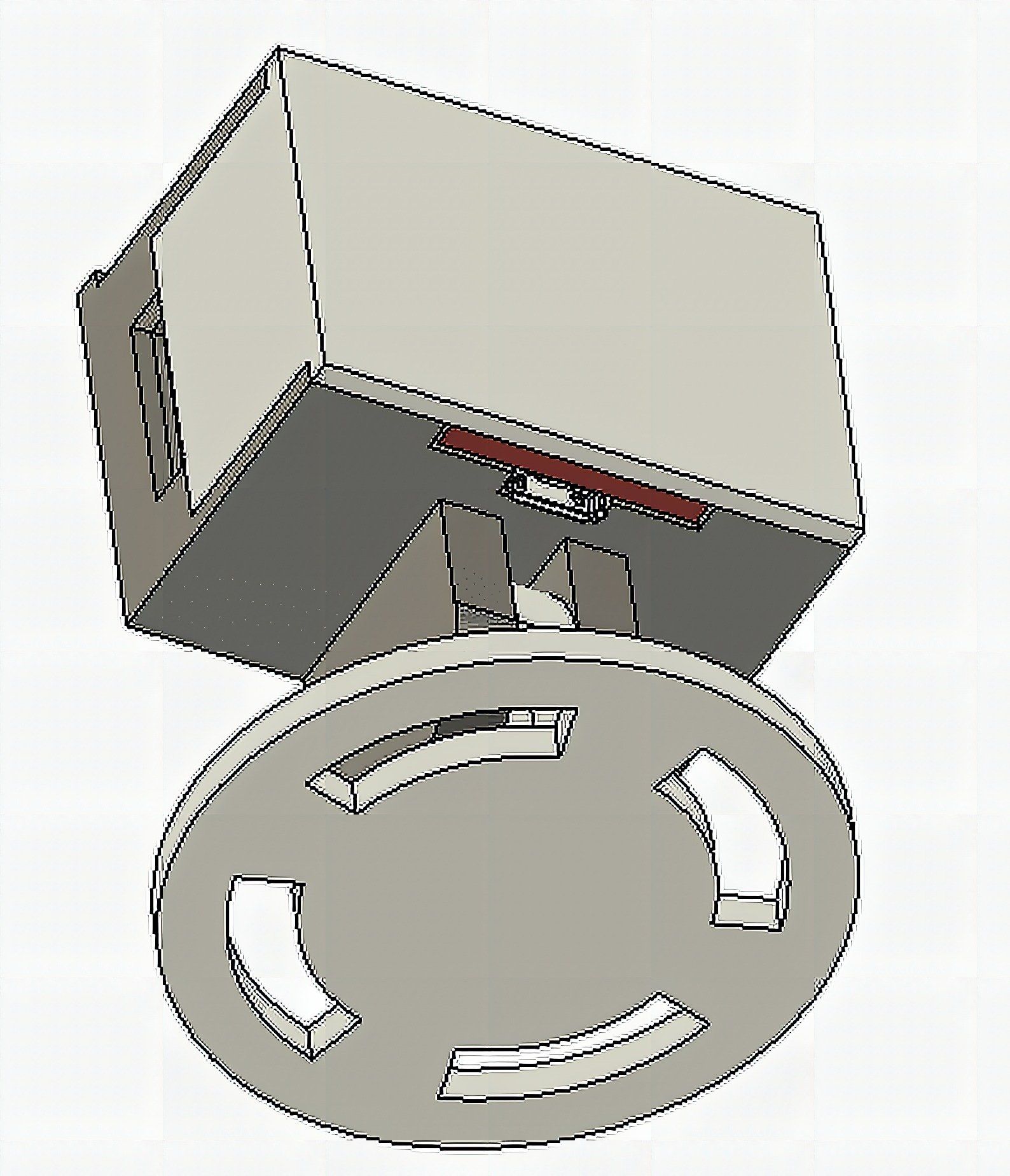
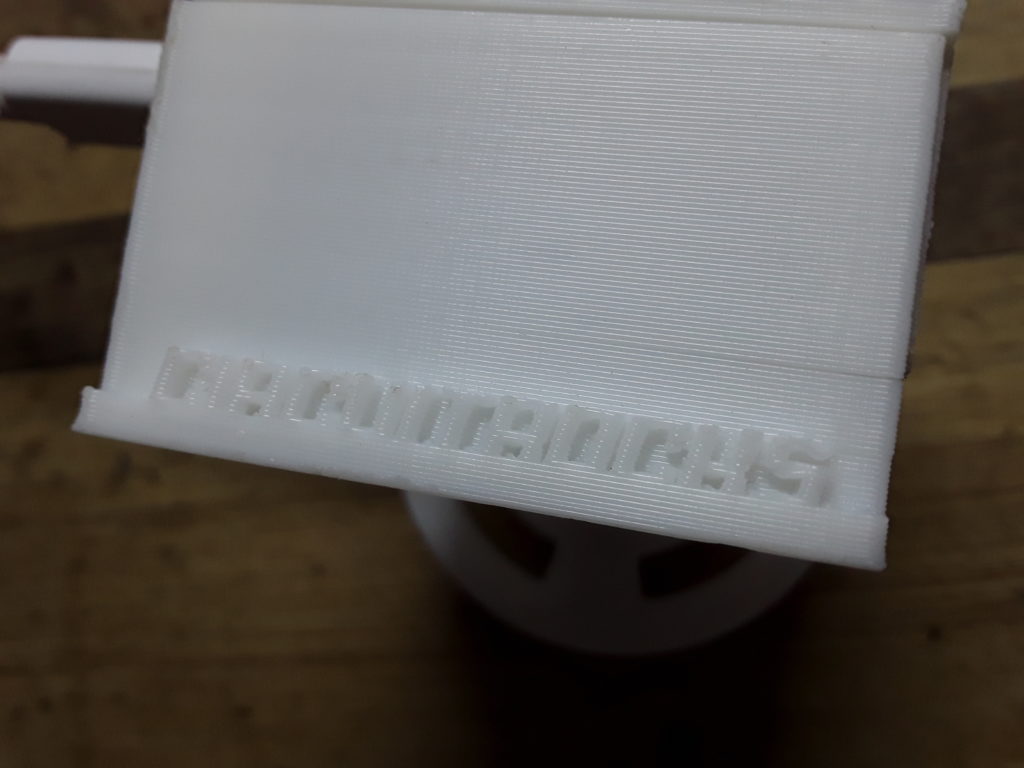
Last last step: put the camera into a nice case.
Now that we have cheap web cam that can stream videos to your devices, it would be nice to have it packaged in a protecting case. There are many options for matching cases for the ESP32-CAM available, but we decided to make our own.

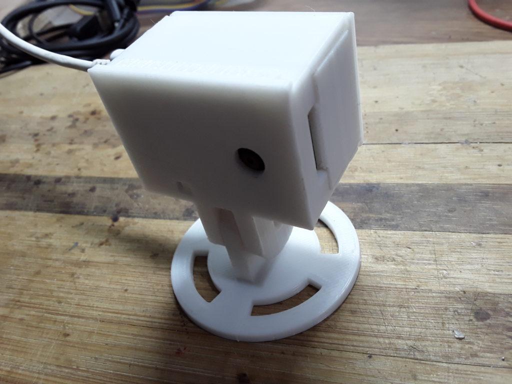
It is a quite simple case, just plugged together with access to the SD card (that we didn’t use in this tutorial). The case has the option of vertical and horizontal adjustment of the viewing angle.
The 3D files for all three parts are available in the 3D folder of the Github repository. At Flarelab the cost of all 3D printed parts was just 360 Pesos.
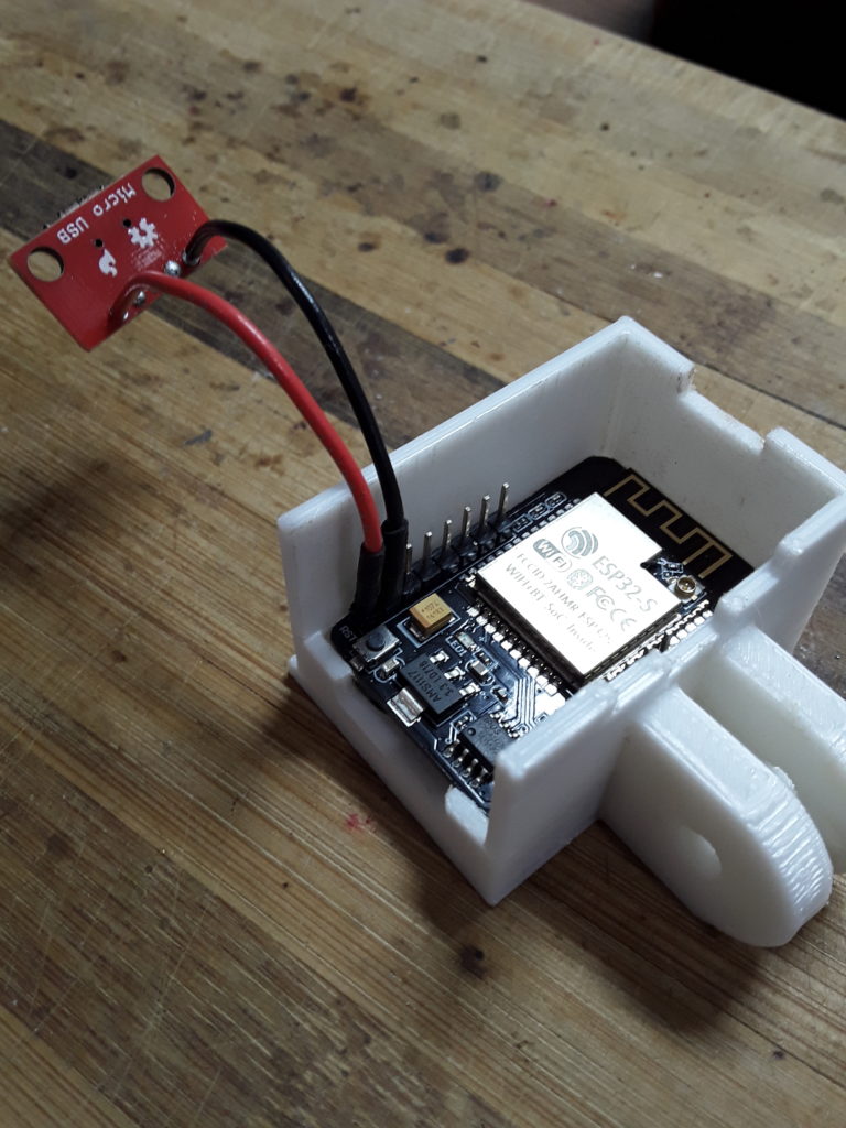
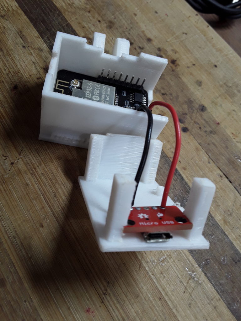
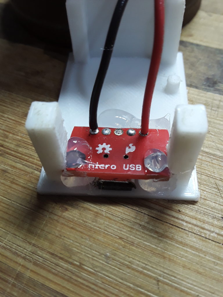
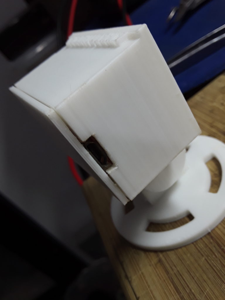
The parts hold the ESP32-CAM board without screws. But some glue might be required to hold the front and back part together. There is as well an opening for a micro USB connector mounted on a breakout board.
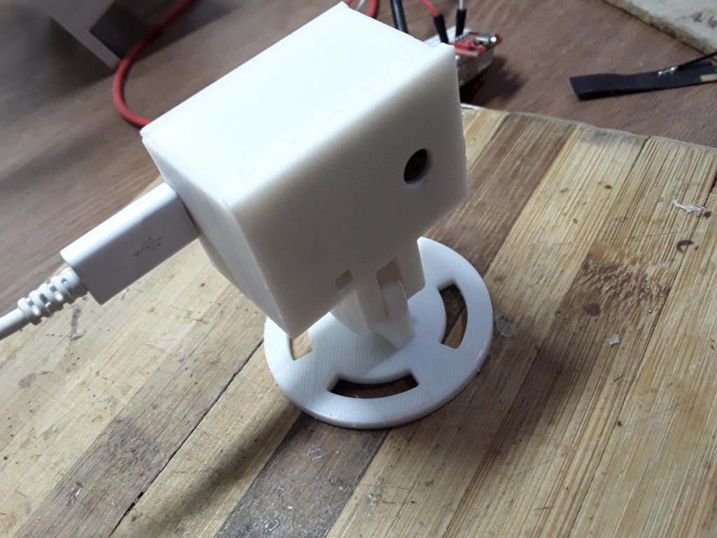
The camera case and the foot are fixed with a 5mm screw. So once you have the right angle you can fix the case by tightening the screw.
The footer has 4 long circled holes that allow to adjust the viewing angle before fixing the case.
Sources:
Source code on Github https://github.com/circuitrocks/ESP32-RTSP
OneButton library https://github.com/mathertel/OneButton
Micro-RTSP sources https://github.com/geeksville/Micro-RTSP
ESP32-CAM https://circuit.rocks/product:2659
Camera case as Fusion360 file https://github.com/circuitrocks/ESP32-RTSP/blob/master/3D/ESP32-CAM-Case.f3z
Camera case STL files for 3D printing https://github.com/circuitrocks/ESP32-RTSP/tree/master/3D
Mounting the camera in the case
Frequently Asked Questions
What does this ESP32-CAM with RTSP video streaming tutorial cover?
The ESP32-CAM is one of the cheapest solutions if you want to add video recording to your IoT project.
Why does my ESP32-CAM fail to flash with 'Failed to connect'?
Hold the GPIO0 button (or jumper IO0 to GND) while clicking Upload. The ESP32-CAM has no auto-reset — manual flash-mode entry is required every upload.
What microSD card works with the ESP32-CAM?
Class 10 / U1 cards up to 32GB formatted FAT32. Larger cards work if formatted FAT32 manually. Sandisk Ultra and Samsung Evo are reliable picks.