
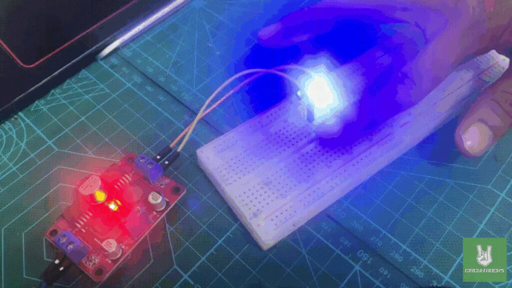
The finger touch circuit is a simple way to see a transistor act as a switch. You wire an NE222 transistor to an LED and a power source, and you feed it 10V from a DC-DC boost converter running off a 5V adapter. The fun part is the two touch wires on the transistor’s base. Pinch both wires and your skin closes the gap. A tiny current sneaks into the base, the transistor turns on, and the LED lights up.
A transistor works like a gate for current. Your touch feeds just enough current into the base to open that gate. Current then flows from the collector to the emitter, and the LED comes on. That same trick sits inside most of the electronics you use every day. Watching the LED react to a touch makes current amplification click in a way a diagram never will.
Build this and you get a real feel for how transistors behave and how a boost converter bumps voltage up. It’s a good first project. Easy to put together, and it shows the idea right away. Once it makes sense, you’ve got a base to build on for bigger stuff, where managing power and amplifying signals start to matter.
Components
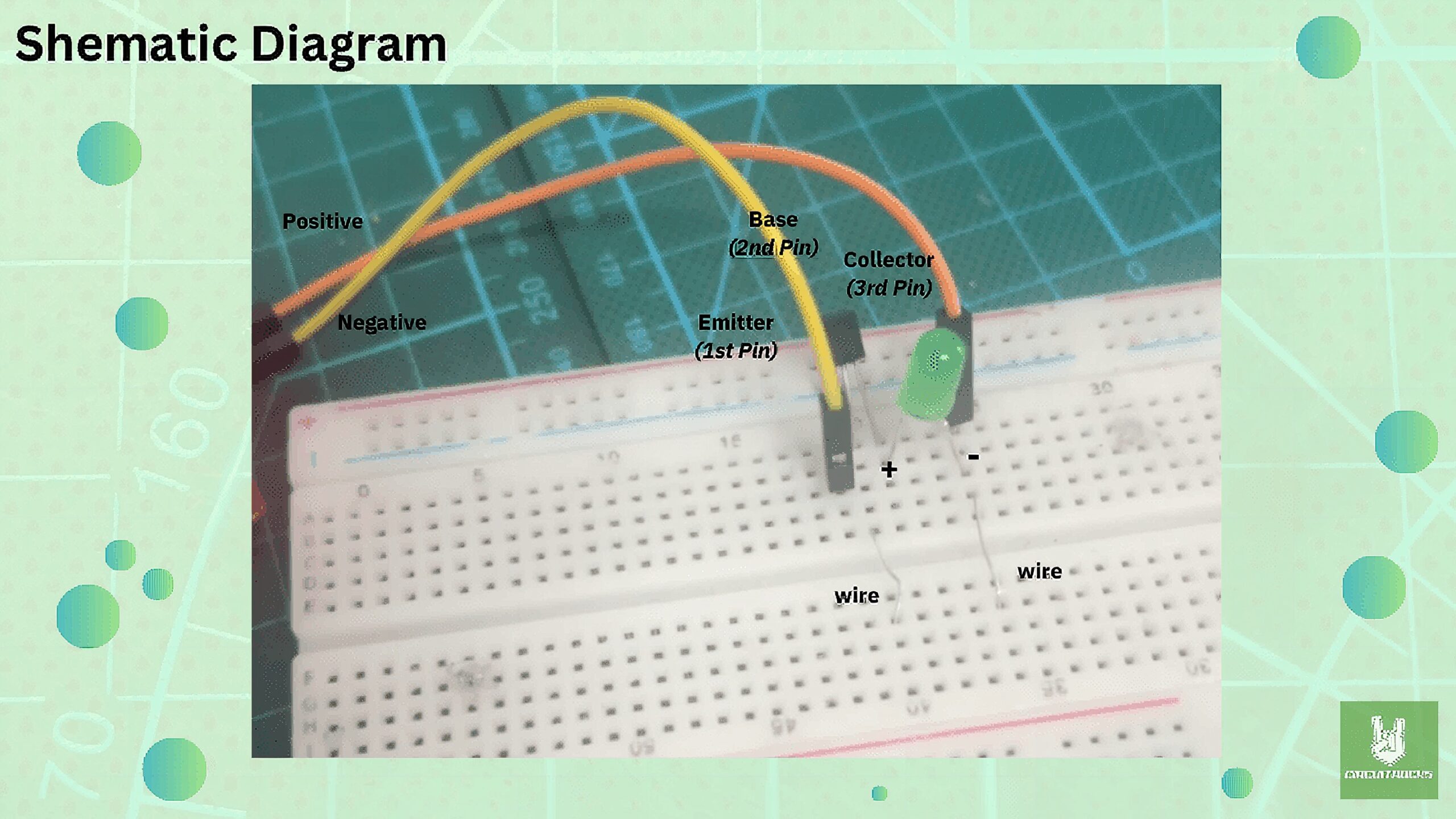
Connection:
Power Source:
- Connect the 5V power adapter to the input of the DC-DC boost converter.
- Adjust the DC-DC boost converter to output 10V.
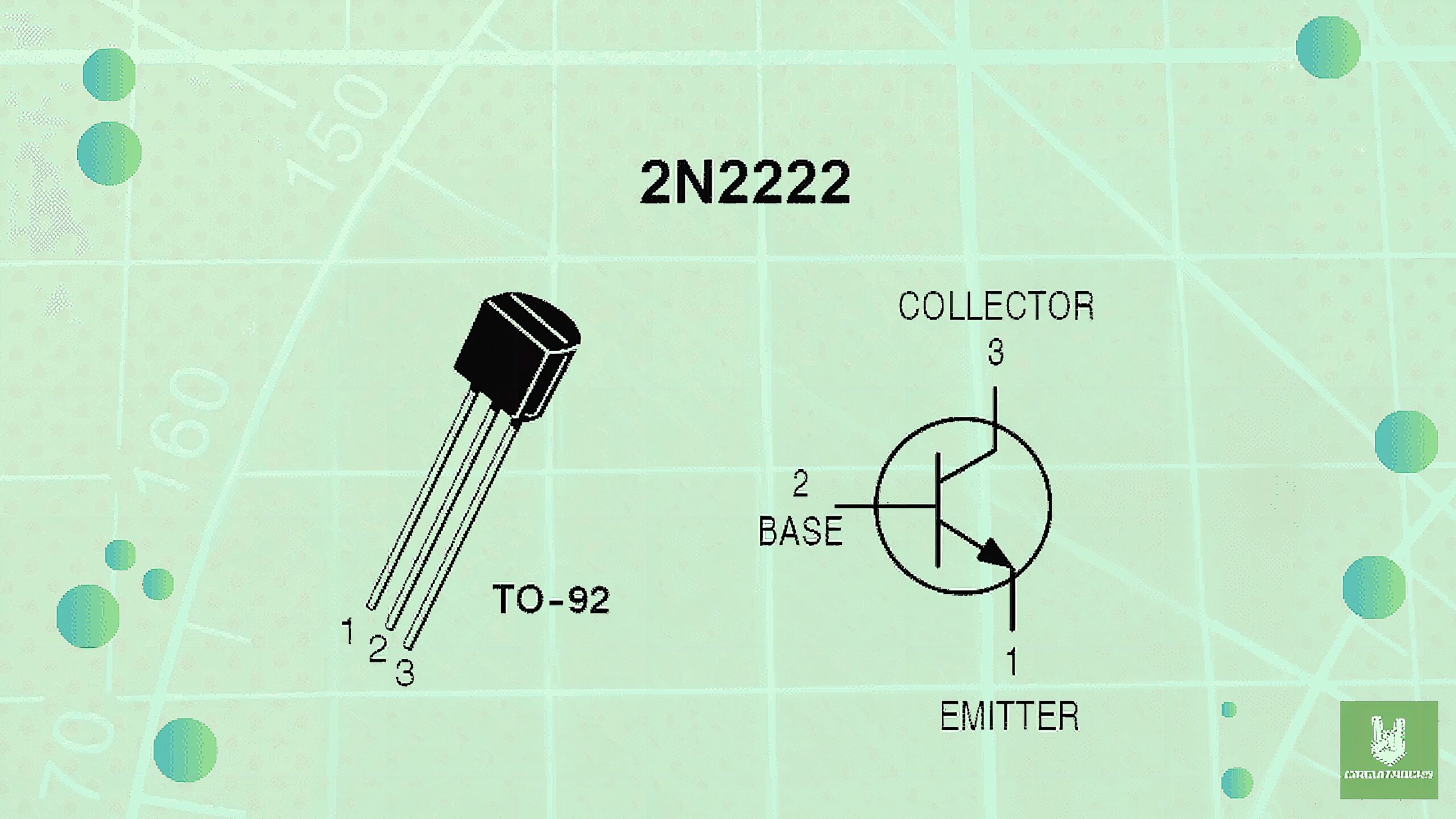
Transistor (NE222):
- Collector (C): Connect the positive terminal of the LED to the collector of the transistor.
- Emitter (E): Connect the emitter directly to the ground (negative terminal) of the power source.
LED:
- Positive (Anode) leg: Connect to the collector (C) of the transistor.
- Negative (Cathode) leg: Connect to the positive output of the 10V power source.
Touch Wires:
- Connect one touch wire to the base (B) of the transistor.
- Connect the second touch wire to the ground (negative terminal) of the power source.
QUICK LINK
Frequently Asked Questions
What does this Finger Touch Circuit tutorial cover?
The finger touch circuit is a straightforward project that introduces the concept of using a transistor as a switch.
What current-limiting resistor should I use for the Finger Touch Circuit build?
Standard 5mm LED: ~220-470Ω from 5V (drops ~13-20mA through the LED). White/blue LEDs have higher Vf (~3V) — use 100-220Ω. NeoPixels have built-in drivers, no resistor.
Can I run many NeoPixels off an Arduino's 5V pin?
No — each pixel draws up to 60mA at full white. Above ~10 pixels, use a separate 5V/2A supply, with the data line through a 300-500Ω resistor and a 1000µF cap across the rails.