In this project, I’ll guide you through creating a Wireless Keypad Data Transmitter with LCD Feedback system. The goal is to build a simple yet functional wireless communication setup. Using an NRF24L01 module, a keypad, and an LCD screen. You’ll learn how to send data wirelessly from the keypad and have it displayed on the LCD in real-time. It demonstrates the ability to send pressed keys from one device (transmitter) to another (receiver) the LCD.
As we go through this project, one of the key lessons you’ll grasp is how to work with different components. Such as the keypad, NRF24L01, and the LCD. You’ll see how to set up the hardware and code each element to function cohesively. The objective here is not just to send data from the keypad to the LCD but to show you how wireless communication between two devices can simplify many applications, eliminating the need for physical wiring between transmitter and receiver.
By the end of this project, you’ll have a better understanding of how to use the RF modules. This hands-on experience will teach you the basic of wireless communication. Which you can apply to other advanced projects like remote control systems or automation. It’s a fun and interactive way to get familiar with integrating multiple components for a practical solution.
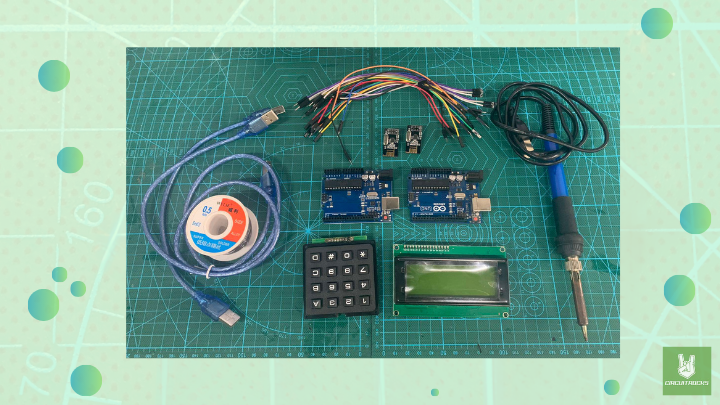
Components:

- RF NRF24L01 (2 pcs)
- Arduino Uno R3 (2pcs)
- Cable Type B (2 pcs)
- Keypad 4×4 Matrix
- LCD 20×4 Yellow
- Male Pin Headers
- Soldering Iron
- Solder Lead
Connections:

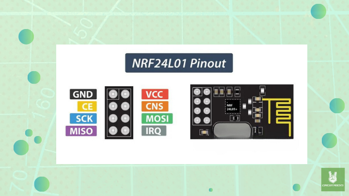
RF NRF24L01 Pinout Diagram

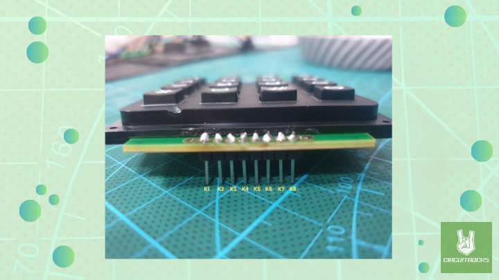
Keypad 4×4 Matrix Diagram
Connections for the Transmitter Arduino:
For Keypad:
- K1→ Pin 2
- K2→ Pin 3
- K3→ Pin 4
- K4→ Pin 5
- K5→ Pin 6
- K6→ Pin 7
- K7→ Pin 8
- K8→ Pin 9
For NRF24L01 as Transmitter:
- VCC → 3.3V (Important: Use 3.3V, not 5V)
- GND → GND
- CE → Pin 9
- CSN → Pin 10
- SCK → Pin 13
- MOSI → Pin 11
- MISO → Pin 12
Connections for the Receiver:
For LCD:
- VCC → 5V
- GND → GND
- SDA → A4
- SCL → A5
For NRF24L01 as Receiver:
- VCC → 3.3V
- GND → GND
- CE → Pin 9
- CSN → Pin 10
- SCK → Pin 13
- MOSI → Pin 11
- MISO → Pin 12
Notes:
- Keypad Library: Go to Sketch > Include Library > Manage Libraries > Search for “Keypad” and install the one by Mark Stanley, Alexander Brevig.
- RF24 Library: Go to Sketch > Include Library > Manage Libraries > Search for “RF24” and install the one by TMRh20.
- LiquidCrystal_I2C Library: Go to Sketch > Include Library > Manage Libraries > Search for “LiquidCrystal I2C” and install the one by Frank de Brabander.
- When working with both the transmitter (keypad) and the receiver (LCD display. You’ll need to run two separate Arduino IDE instances simultaneously. Each IDE should be configured to a different COM port so that your computer can recognize both microcontrollers
- If you encounter a port conflict, make sure each microcontroller is properly assigned to a unique COM port.
- Ensure that the NRF24L01 modules are properly powered. They require a stable 3.3V power source, not 5V, to function correctly. Use a capacitor across the power lines if needed to stabilize power.
Code:
Transmitter Code with Keypad and NRF24L01:
#include <Keypad.h>
#include <SPI.h>
#include <nRF24L01.h>
#include <RF24.h>

// Define the number of rows and columns
const byte ROWS = 4;
const byte COLS = 4;

// Define the symbols on the keypad buttons
char keys[ROWS][COLS] = {
  {'1', '4', '7', '*'},
  {'2', '5', '8', '0'},
  {'3', '6', '9', '#'},
  {'A', 'B', 'C', 'D'}
};

// Connect keypad ROW0, ROW1, ROW2, and ROW3 to these Arduino pins
byte rowPins[ROWS] = {2, 3, 4, 5};
// Connect keypad COL0, COL1, COL2, and COL3 to these Arduino pins
byte colPins[COLS] = {6, 7, 8, 9};

// Create the Keypad object
Keypad keypad = Keypad(makeKeymap(keys), rowPins, colPins, ROWS, COLS);

// NRF24L01 configuration
RF24 radio(9, 10); // CE, CSN pins for NRF24L01
const byte address[6] = "00001"; // Address for communication

void setup() {
  Serial.begin(9600);

  // Initialize NRF24L01 radio
  radio.begin();
  radio.openWritingPipe(address); // Open the writing pipe
  radio.setPALevel(RF24_PA_MIN);  // Set the power level
  radio.stopListening();          // Set as transmitter
}

void loop() {
  char key = keypad.getKey(); // Get the pressed key from the keypad
  if (key) {
    Serial.println(key); // Print the pressed key to the serial monitor

    // Send the key wirelessly using NRF24L01
    radio.write(&key, sizeof(key)); // Send the key character
  }
}
Explanation:
- Keypad Setup: The code reads the pressed key from the keypad using the Keypad library.
- NRF24L01 Setup: The RF24 object (
radio) is initialized to communicate over the 2.4 GHz band. The writing pipe is opened to send data to a specific address. - Sending the Key: Whenever a key is pressed, it is printed to the serial monitor and also sent via the NRF24L01 module to the receiver.
Receiver Code (LCD and NRF24L01)
#include <Wire.h>
#include <LiquidCrystal_I2C.h>
#include <SPI.h>
#include <nRF24L01.h>
#include <RF24.h>

LiquidCrystal_I2C lcd(0x27, 16, 2); // Set the LCD address to 0x27 for a 16x2 LCD

RF24 radio(9, 10); // CE, CSN pins for NRF24L01
const byte address[6] = "00001"; // Same address as the transmitter

void setup() {
  // Initialize LCD
  lcd.begin(16, 2);
  lcd.backlight();
  lcd.setCursor(0, 0);
  lcd.print("Waiting for key");

  // Initialize NRF24L01
  radio.begin();
  radio.openReadingPipe(0, address); // Open the reading pipe
  radio.setPALevel(RF24_PA_MIN);     // Set the power level
  radio.startListening();            // Set as receiver
}

void loop() {
  if (radio.available()) {
    char receivedKey;
    radio.read(&receivedKey, sizeof(receivedKey)); // Read the received key

    // Display the received key on the LCD
    lcd.clear();
    lcd.setCursor(0, 0);
    lcd.print("Key Pressed:");
    lcd.setCursor(0, 1);
    lcd.print(receivedKey);
  }
}
Explanation:
- LCD Setup: The LiquidCrystal_I2C library is used to display the received key on the 16×2 LCD.
- NRF24L01 Setup: The receiver listens for data from the transmitter and reads the key data sent from the keypad.
- Displaying the Key: Once the key is received, it is displayed on the LCD.


