
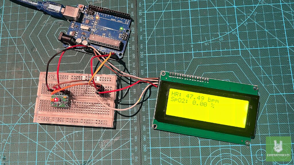
In this project, I will guide you in creating a simple health-monitoring device. That measures heart rate and oxygen saturation (SpO2) and displays the data on an I2C LCD screen. By simply placing your finger on the sensor, the device will show your heart rate and SpO2. By the end of this tutorial, you’ll have built a fully functional health monitoring device. That you can use for personal health tracking or as part of a larger system.
We’ll be using the MAX30100 sensor, which measures heart rate and oxygen saturation. By detecting changes in light absorption in your blood. In addition, we’ll use an I2C LCD, a user-friendly display that communicates with the Arduino via the I2C protocol. This display offers a simple and efficient way to show data making it easy to monitor your health at a glance.
This project is a great way to get hands-on experience with health-monitoring devices. As you follow this guide, you’ll gain valuable skills. Which are crucial for modern electronics and healthcare technology.
Components
Connections:
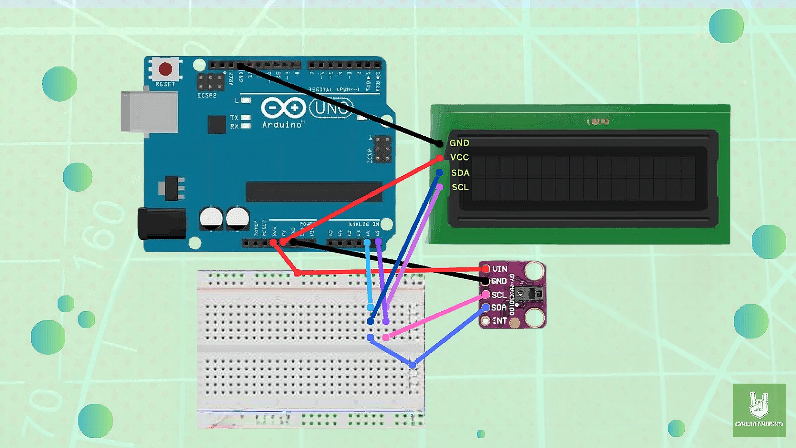
- 5V from Arduino goes to VIN (VCC) on the MAX30100 and the VCC on the LCD.
- GND from Arduino goes to GND on both the MAX30100 and the LCD.
- SDA (A4) from Arduino is shared by both MAX30100 and LCD (connected via breadboard).
- SCL (A5) from Arduino is shared by both MAX30100 and LCD (connected via breadboard).
Notes
Before we move forward, you may remember that we mentioned before that the RCWL-0530 version has a serious design issue. Let us see how to resolve that first.
You can view the schematic diagram of the module below:
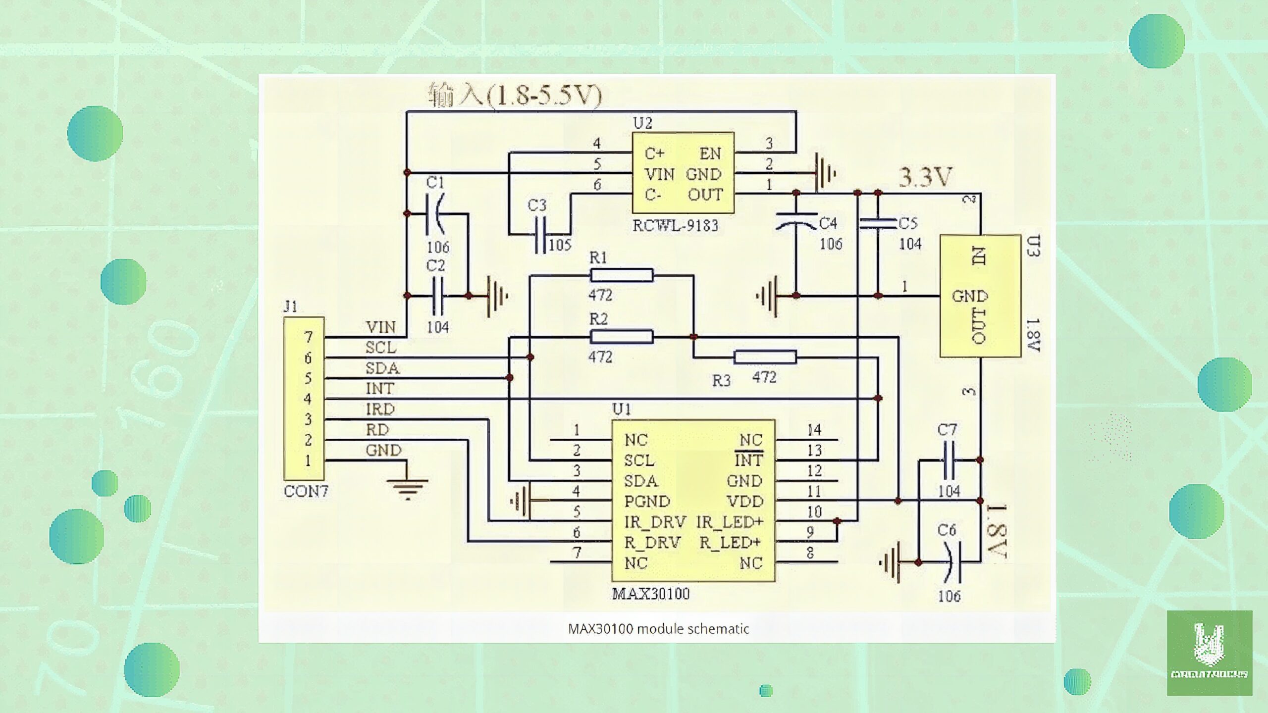
MAX30100 sensor module consists of two LDO regulators. This is because the MAX30100 IC requires 1.8V and the LEDs require 3.3V to function properly. Now refer to the schematic diagram of the module and notice that the SDA, SCL, and INT lines are connected to 1.8V via 4.7k ohm pull-up resistors. This is a serious design issue because now the sensor will not properly work with microcontrollers with higher logic levels e.g. Arduino in our case. The I2C device will not be recognized.
One way to resolve the issue stated above is to remove the three pull-up resistors shown in the diagram below and use external ones instead.
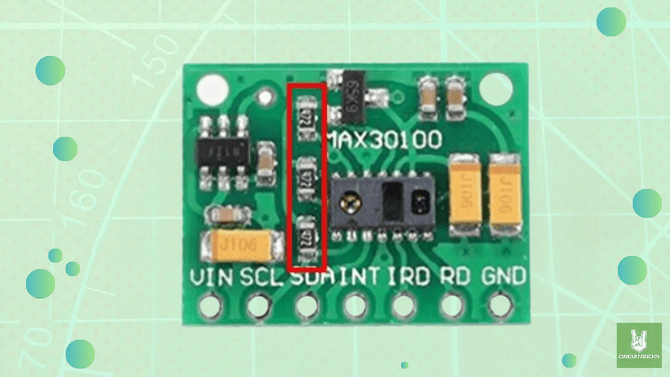
One way to resolve the issue stated above is to remove the three pull-up resistors shown in the diagram below. You can easily remove them using a soldering iron. After you have removed the resistors, you are good to go and can connect your module with Arduino.
Components
Code:
#include <Wire.h>
#include <LiquidCrystal_I2C.h>
#include "MAX30100_PulseOximeter.h" // Set the LCD address to 0x27 for a 16x2 I2C display
LiquidCrystal_I2C lcd(0x27, 16, 2); // PulseOximeter instance for the MAX30100 sensor
PulseOximeter pox; #define REPORTING_PERIOD_MS 1000 uint32_t tsLastReport = 0; // Callback function when a beat is detected
void onBeatDetected()
{ Serial.println("Beat detected!");
} void setup() { // Initialize serial communication for debugging Serial.begin(115200); // Initialize the LCD lcd.begin(16, 2); lcd.backlight(); // Print "Hello, World!" on the LCD lcd.setCursor(0, 0); lcd.print("Hello, World!"); // Initialize the PulseOximeter sensor Serial.print("Initializing MAX30100..."); if (!pox.begin()) { Serial.println("FAILED"); lcd.setCursor(0, 1); lcd.print("Sensor Fail"); for(;;); // Halt execution if initialization fails } else { Serial.println("SUCCESS"); lcd.setCursor(0, 1); lcd.print("Sensor Ready"); } // Register a callback for when a beat is detected pox.setOnBeatDetectedCallback(onBeatDetected);
} void loop() { // Update the PulseOximeter readings pox.update(); // Periodically display heart rate and SpO2 readings on the LCD if (millis() - tsLastReport > REPORTING_PERIOD_MS) { float heartRate = pox.getHeartRate(); float SpO2 = pox.getSpO2(); // Print readings to the Serial Monitor Serial.print("Heart rate: "); Serial.print(heartRate); Serial.print(" bpm / SpO2: "); Serial.print(SpO2); Serial.println(" %"); // Display the readings on the LCD lcd.clear(); lcd.setCursor(0, 0); lcd.print("HR: "); lcd.print(heartRate); lcd.print(" bpm"); lcd.setCursor(0, 1); lcd.print("SpO2: "); lcd.print(SpO2); lcd.print(" %"); tsLastReport = millis(); // Update the reporting timestamp }
}
QUICK LINK
Frequently Asked Questions
What does this Monitoring Heart Rate and Oxygen Using the MAX30100 tutorial cover?
In this project, I will guide you in creating a simple health-monitoring device.
What's the working voltage of the Monitoring Heart Rate and Oxygen Using the MAX30100?
Check the Sample Code section for the exact pinout — most maker-grade sensors run on 3.3V or 5V. Wire VCC to the matching rail, GND common with your MCU, data to a digital or analog pin.
Why does the Monitoring Heart Rate and Oxygen Using the MAX30100 read garbage or saturated values?
Three usual causes: wrong voltage rail, missing pull-up resistor on I2C lines (4.7k–10k to VCC), or a floating data pin. Double-check wiring against the diagram, then probe with a multimeter.