
Espressif Systems has developed its own wireless protocol for its ESPx series of chips. It boasts a fast wireless connection without needing to connect to a WiFi network. Join me as we both discover what it’s capable of!
Introduction
The need for fast data transmission stems from the fact that smart devices usually rely on battery power. For instance, an ESP chip needs its transceiver to be always active when transmitting data. Undeniably, an active transceiver consumes more power than an idle one. Moreover, using a web service to connect 2 ESP devices will always be slower than a direct connection. HTTP packets just hold too much overhead for real-time applications.
Take a look at these power consumption figures taken from Espressif’s datasheets.
| Mode | ESP8266 | ESP32 |
| Deep Sleep | 0.01mA | 0.01mA |
| Sleep | 0.9mA | 0.8mA |
| CPU only | 15mA | 20mA |
| WiFi RX | 56mA | 100mA |
| WiFi TX | 320mA | 400mA |
The ESP8266 consumes 32,000x more power in transmission than in deep sleep. That’s a number way too large to ignore when developing a device that runs on a battery.
We need a communication protocol that sends data in the blink of an eye. A fast protocol that can lessen transmission time, so we can put the ESP8266 into sleep.
ESP-NOW
ESP-NOW is a wireless communication protocol developed by Espressif Systems for its ESPx line of chips. It allows ESP devices to communicate directly without connecting to a WiFi network.
Though it still complies with WiFi’s 802.11n standard, it is actually different. It uses a technology similar to wireless keyboards and mice. Similar that it needs to pair with themselves first to initiate communication. When paired, devices automatically connect when reset. Unlike when using WiFi, where an ESP web client needs at least a couple of seconds to connect to an Access Point.
Management Action Frame
802.11n has a class of data called Management Action Frame (MAF). It allows short framed packets of data to be passed between ESP chips regardless of wifi network connection status.
ESP-NOW uses a sub-category of MAFs called vendor-specific, and vendor-specific protected. You use vendor-specific protected when you enable encryption. Every vendor-specific packet contains a vendor ID that allows the chip to filter-out broken packets.
Advantages
- Supports a maximum of 20 nodes.
- It works everywhere. It does not require a router or a DHCP server.
- No overhead.
- Faster data transmission since it does not need to connect to a Wifi Access Point.
Disadvantages
- Data packet is limited to 250 bytes.
- Limited to up to 10 encrypted peers.
Preparing the Hardware
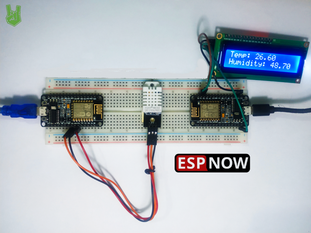
In our example, we are going to interface a DHT22 sensor into NODEMCU1. Then, send it to NODEMCU2 every 2 seconds using ESP-NOW. Lastly, we make NODEMCU2 display the data into an LCD display.
In order to do all of that, we need:
- 2 x NodeMCU ESP8266 boards
- 1 x DHT22 sensor
- 1 x LCD 1602 I2C module
- Jumper wires
- Breadboard
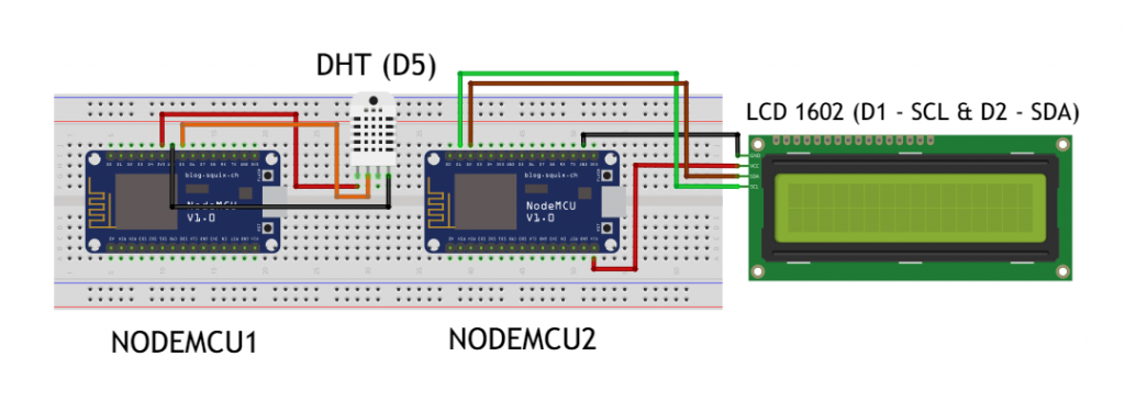
Connect the parts as shown below.
Code for Controller (Sender)
#include <ESP8266WiFi.h>
#include <espnow.h>
#include <DHT.h>
#define DHTPin D5
#define DHTType DHT22
DHT dht(DHTPin, DHTType);
float t,h; uint8_t broadcastAddress[] = {0xB4, 0xE6, 0x2D, 0x4A, 0x3E, 0x24}; typedef struct struct_message { float a; float b;
} struct_message; struct_message myData; void OnDataSent(uint8_t *mac_addr, uint8_t sendStatus) { Serial.print("Last Packet Send Status: "); if (sendStatus == 0) { Serial.println(Sent); } else { Serial.println(Failed); }
} void setup() { Serial.begin(115200); delay(100); lcd.begin(); delay(10); dht.begin(); WiFi.mode(WIFI_STA); if (esp_now_init()!= 0) { Serial.println("Error initializing ESP-NOW"); return; } esp_now_set_self_role(ESP_NOW_ROLE_CONTROLLER); esp_now_register_send_cb(OnDataSent); esp_now_add_peer(broadcastAddress, ESP_NOW_ROLE_SLAVE, 1, NULL, 0);
} void loop() { t = dht.readTemperature(); delay(10); h = dht.readHumidity(); delay(10); myData.a = t; myData.b = h; esp_now_send(broadcastAddress, (uint8_t *) &myData, sizeof(myData)); lcd.clear(); delay(2000);
}
Code Explanation
First, install DHT.h using the library manager. ESP8266WiFi.h and espnow.h are built-in libraries from the Arduino ESP8266 core so no need to add them.
#include <ESP8266WiFi.h>
#include <espnow.h>
#include <DHT.h>
#define DHTPin D5
#define DHTType DHT22
DHT dht(DHTPin, DHTType);
float t,h;
Set the MAC address of the receiver to pair.
uint8_t broadcastAddress[] = {0xB4, 0xE6, 0x2D, 0x4A, 0x3E, 0x24};Compose a message structure to contain your data. In our example, we only need 2 floats to hold our temperature and humidity readings, but you can send other data types such as characters and booleans as well. Just keep in mind that ESP-NOW only supports a maximum of 250 bytes payload.
After composing the message structure, we create an object called myData.
typedef struct struct_message { float a; float b;
} struct_message; struct_message myData;
Next, declare a callback function that triggers when data is sent. The function contains an if statement that tells you the packet delivery status.
void OnDataSent(uint8_t *mac_addr, uint8_t sendStatus) { Serial.print("Last Packet Send Status: "); if (sendStatus == 0) { Serial.println(Sent); } else { Serial.println(Failed); }
}
In the setup section, we initialize the serial monitor and the DHT sensor. Then, we set the ESP module to a WiFi station. This enables the board to connect to other ESP modules.
Next, we set the role of the board as the controller with esp_now_set_self_role(ESP_NOW_ROLE_CONTROLLER). Then, we register the callback function we made earlier to trigger when data is sent to the slave.
Finally, we pair with the slave device using esp_now_add_peer().
void setup() { Serial.begin(115200); delay(10); dht.begin(); WiFi.mode(WIFI_STA); if (esp_now_init()!= 0) { Serial.println("Error initializing ESP-NOW"); return; } esp_now_set_self_role(ESP_NOW_ROLE_CONTROLLER); esp_now_register_send_cb(OnDataSent); esp_now_add_peer(broadcastAddress, ESP_NOW_ROLE_SLAVE, 1, NULL, 0);
}
Use the loop section of the controller to prepare and send the data to the slave. In our case, we get the temperature and humidity readings using DHT functions. Then, we store them into our message structure myData. Lastly, we send the data using esp_now_send() then pause for 2 seconds using delay so we don’t overload the receiver.
void loop() { t = dht.readTemperature(); delay(10); h = dht.readHumidity(); delay(10); myData.a = t; myData.b = h; esp_now_send(broadcastAddress, (uint8_t *) &myData, sizeof(myData)); lcd.clear(); delay(2000);
}
Code for Slave (Receiver)
#include <ESP8266WiFi.h>
#include <espnow.h>
#include <Wire.h>
#include <LiquidCrystal_I2C.h>
LiquidCrystal_I2C lcd(0x27, 16, 2); typedef struct struct_message { float a; float b;
} struct_message; struct_message myData; void OnDataRecv(uint8_t * mac, uint8_t *incomingData, uint8_t len) { lcd.clear(); memcpy(&myData, incomingData, sizeof(myData)); lcd.setCursor(0, 0); lcd.print("Temp: ");lcd.print(myData.b); lcd.setCursor(0, 1); lcd.print("Humidity: ");lcd.print(myData.c); } void setup() { Serial.begin(115200); lcd.begin(); WiFi.mode(WIFI_STA); if (esp_now_init()!= 0) { Serial.println("Error initializing ESP-NOW"); return; } esp_now_set_self_role(ESP_NOW_ROLE_SLAVE); esp_now_register_recv_cb(OnDataRecv);
} void loop() { }
Code Explanation
Aside from the ESP libraries, we need to install the library for the LCD 1602 module. Determine the I2C address then set the number of rows and columns the LCD would use.
#include <Wire.h>
#include <LiquidCrystal_I2C.h>
LiquidCrystal_I2C lcd(0x27, 16, 2);
Next, compose the message structure. Make sure it matches with the other device.
typedef struct struct_message { float a; float b;
} struct_message;
Then, declare a call back function that runs when data is received. In our case, we use the LCD functions to display the data we receive from the controller device.
void OnDataRecv(uint8_t * mac, uint8_t *incomingData, uint8_t len) { lcd.clear(); memcpy(&myData, incomingData, sizeof(myData)); lcd.setCursor(0, 0); lcd.print("Temp: ");lcd.print(myData.b); lcd.setCursor(0, 1); lcd.print("Humidity: ");lcd.print(myData.c); }Our setup section should look exactly the same besides a few lines. Since we need this device as the receiver, we set it as a slave device using esp_now_set_self_role(ESP_NOW_ROLE_SLAVE). Lastly, we register the receiver callback function so that it triggers when data is received from the controller.
void setup() { Serial.begin(115200); lcd.begin(); WiFi.mode(WIFI_STA); if (esp_now_init()!= 0) { Serial.println("Error initializing ESP-NOW"); return; } esp_now_set_self_role(ESP_NOW_ROLE_SLAVE); esp_now_register_recv_cb(OnDataRecv);
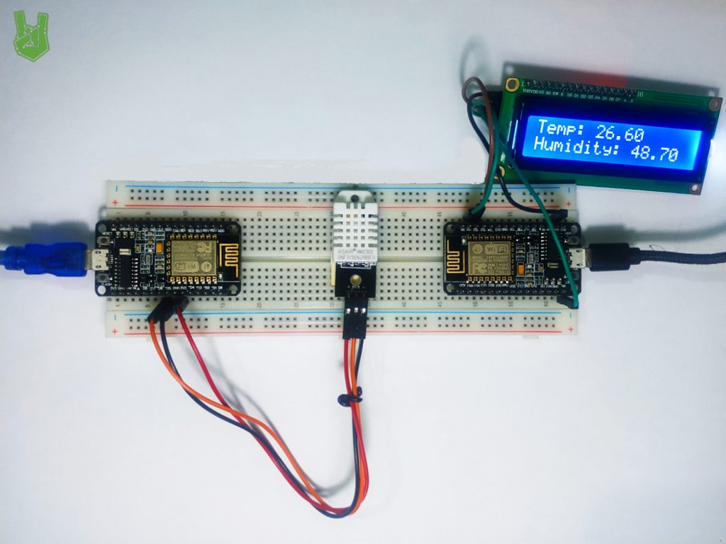
}Demonstration
Using two supplies (in my case two USB ports), power the NodeMCU boards. You should see something like this.
Frequently Asked Questions
What does this ESP-NOW: Peer-to-Peer Communication Between ESP boards tutorial cover?
Espressif Systems has developed its own wireless protocol for its ESPx series of chips.
What's the working voltage of the ESP-NOW: Peer-to-Peer Communication Between ESP boards?
Check the Sample Code section for the exact pinout — most maker-grade sensors run on 3.3V or 5V. Wire VCC to the matching rail, GND common with your MCU, data to a digital or analog pin.
Why does the ESP-NOW: Peer-to-Peer Communication Between ESP boards read garbage or saturated values?
Three usual causes: wrong voltage rail, missing pull-up resistor on I2C lines (4.7k–10k to VCC), or a floating data pin. Double-check wiring against the diagram, then probe with a multimeter.