
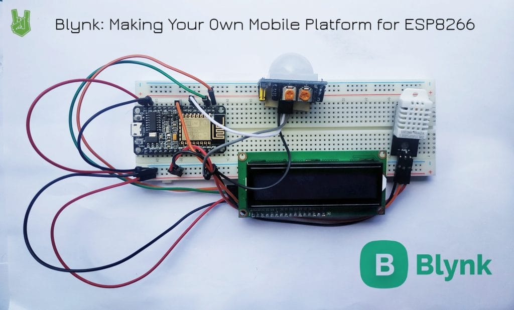
In this tutorial, we are going to design a mobile platform that displays DHT data from an ESP8266 using the Blynk smartphone application.
Blynk
Blynk is a smartphone application that connects any hardware to the cloud. It lets you design an interactive interface to control and manage a myriad of hardware platforms, including Arduino, ESP266/ESP32, and Raspberry Pi.
The app supports Android and IOS devices. It boasts a friendly interface where you can easily drag and drop widgets like switches, buttons, and graphs to represent your data.
Moreover, Blynk is free for non-commercial use. So you’re getting these features that can potentially ease your life or small business without spending a cent.
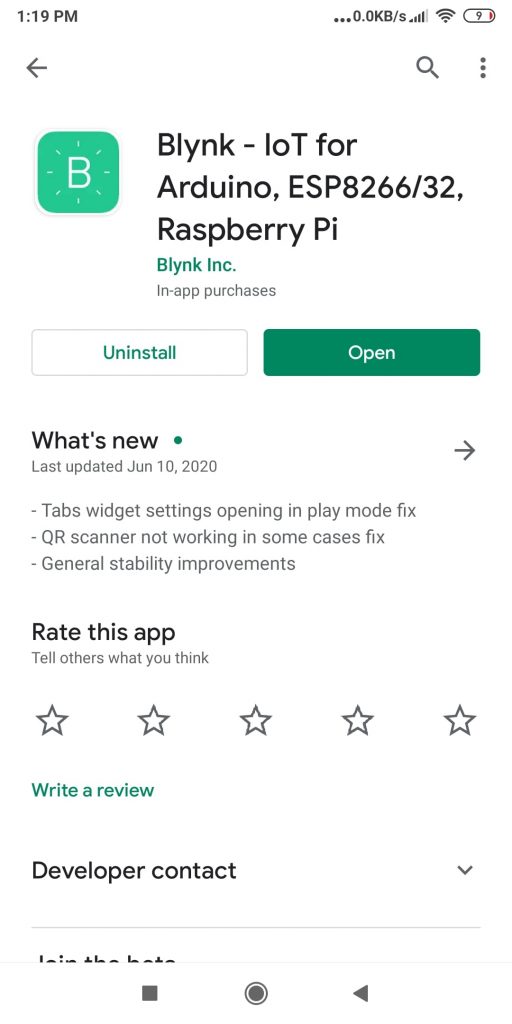
In order to use Blynk, you need to download and install their app.
You are going to need the Blynk library as well.
Blynk library: https://github.com/blynkkk/blynk-library
Alternatively, you can search for the library in the Arduino IDE’s library manager.
How Blynk Works
A Blynk process starts with hardware connecting to the cloud. First, the hardware opens either keep-alive ssl/tls connection on port 443 (9443 for local servers) or keep-alive plain tcp/ip connection on port 8080. Blynk Cloud acts as the middle man for the messages between hardware and app.
Blynk does not use HTTP or MQTT for communicating. It uses its own protocol which we’ll examine later.
In layman’s terms, every time you input something in the app, say a button, the message goes to the Blynk Cloud first, then using Blynk’s own protocol, travels to your hardware.

Blynk System (Image Credit: Blynk)
Blynk protocol
Hardware side protocol
Blynk data packets travel server-hardware and vice versa using this structure:
| Command | Message ID | Length/Status | Body |
|---|---|---|---|
| 1 byte | 2 bytes | 2 bytes | Variable |
Mobile app side protocol
Server-mobile app communication uses the same structure.
| Command | Message ID | Length/Status | Body |
|---|---|---|---|
| 1 byte | 2 bytes | 4 bytes | Variable |
Websockets web side protocol
Web sockets require a header in their structure.
| Websocket header | Command | Message ID | Body |
|---|---|---|---|
| 1 byte | 2 bytes | Variable |
When command code == 0, than message structure is next:
| Websocket header | Command | Message ID | Response code |
|---|---|---|---|
| 1 byte | 2 bytes | 4 bytes |
Here is the complete list of possible response codes and possible command codes.
Some Important Things
Blynk does not use void(loop) and delay
Developers discourage the use of void(loop) for sending data. Timers and separate functions must be used instead.
The main reason for this is that it risks flooding the server. Microcontrollers run at incredible speeds. If a code is left unoptimized, a loop sketch can send hundreds and thousands of messages into the server. When it happens, Blynk automatically disconnects your device to prevent the server from crashing.
Virtual Pins
Virtual pins are pins that you can control without writing new code. This greatly simplifies things especially if you’re only using basic read and write on your device. Here’s how you use them:
1. First, upload this sketch on your device.
#define BLYNK_PRINT Serial
#include <ESP8266WiFi.h>
#include <BlynkSimpleEsp8266.h> char auth[] = "YourAuthToken";
char ssid[] = "YourNetworkName";
char pass[] = "YourPassword"; void setup()
{ Serial.begin(115200); Blynk.begin(auth, ssid, pass);
} void loop()
{ Blynk.run();
}
2. Then, in your app, add a widget and the pin you want to control. For instance, if we connect an LED to pin 5, add a button widget particularly for pin 5.
3. Lastly, press the button in the App to turn your LED on or off.
Preparing the Hardware
In this project, we are going to read the temperature and humidity values from a DHT sensor and feed them to Blynk every 2 seconds. Additionally. we are going to set up a PIR sensor as a motion sensor. Both devices should appear on our smartphones.
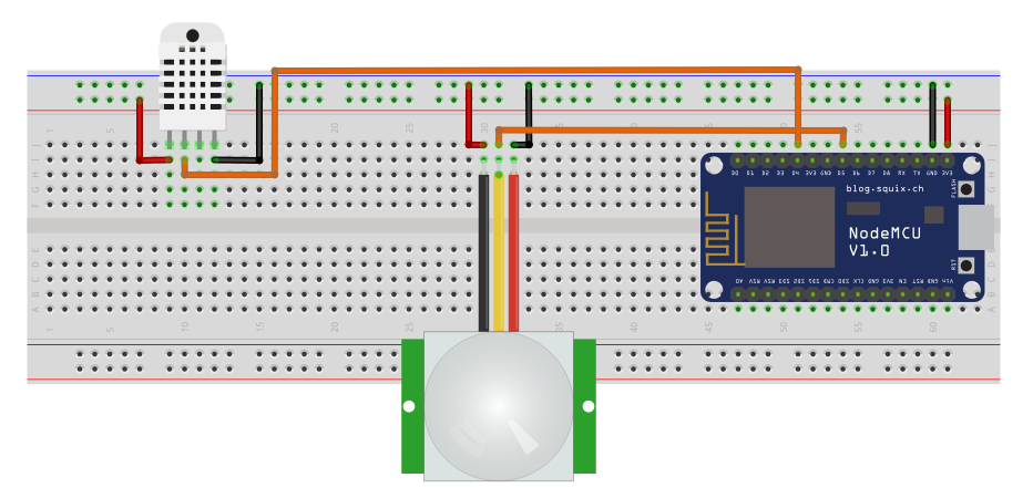
In order to do these, connect the components below as shown.
- NodeMCU
- DHT sensor
- PIR sensor
- Jumper wires
- Breadboard
Setting up the App
First, install the app from the Playstore/App Store.
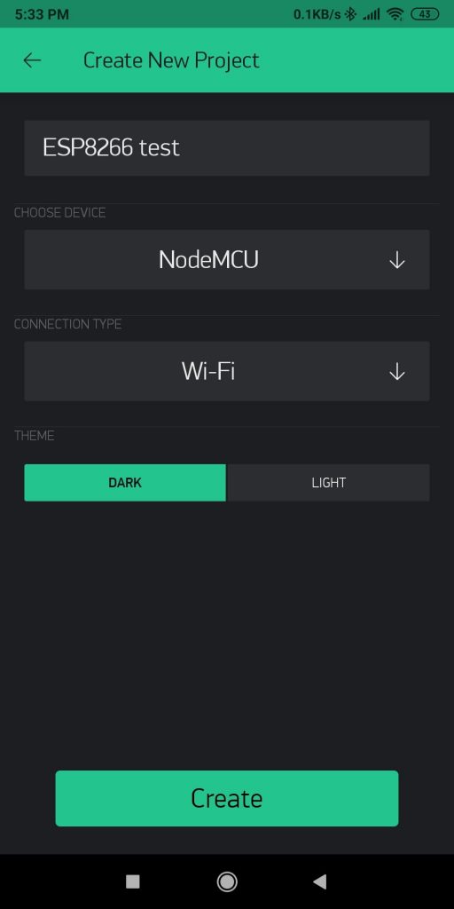
In order to enjoy Blynk’s features, you must first create an account. Once logged in, create a new project that would contain your ESP8266 controls and displays.
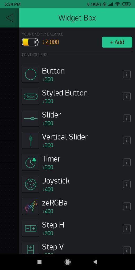
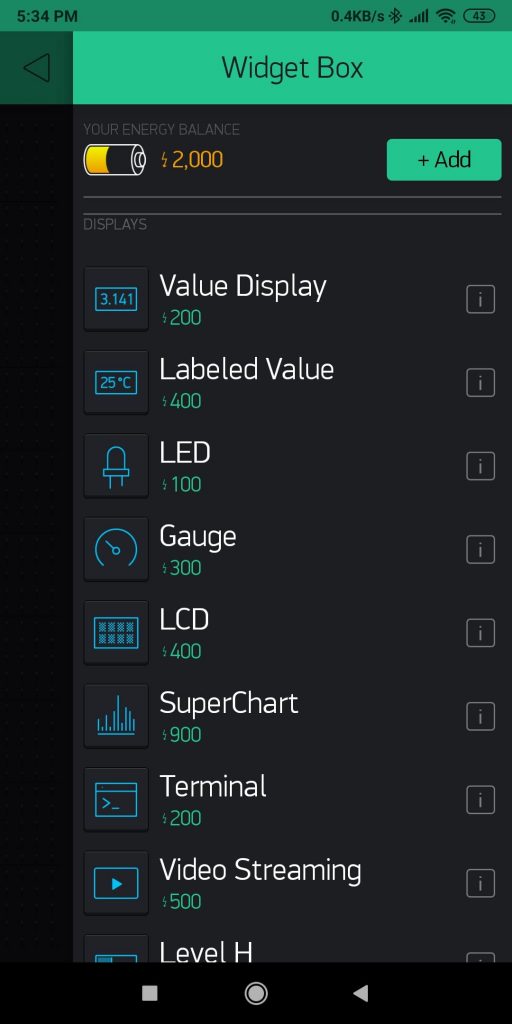
Blynk offers a variety of widgets that you can use. There are controllers in which you can use as an input to trigger an action in your device and displays which serve as an interface to monitor your data. To summon the widget box, click the plus button on the top or tap anywhere on the canvas.
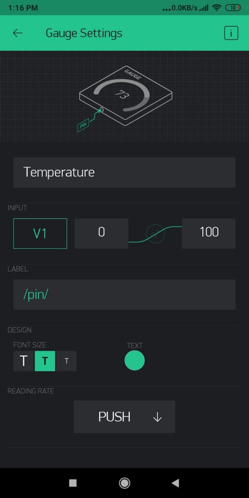
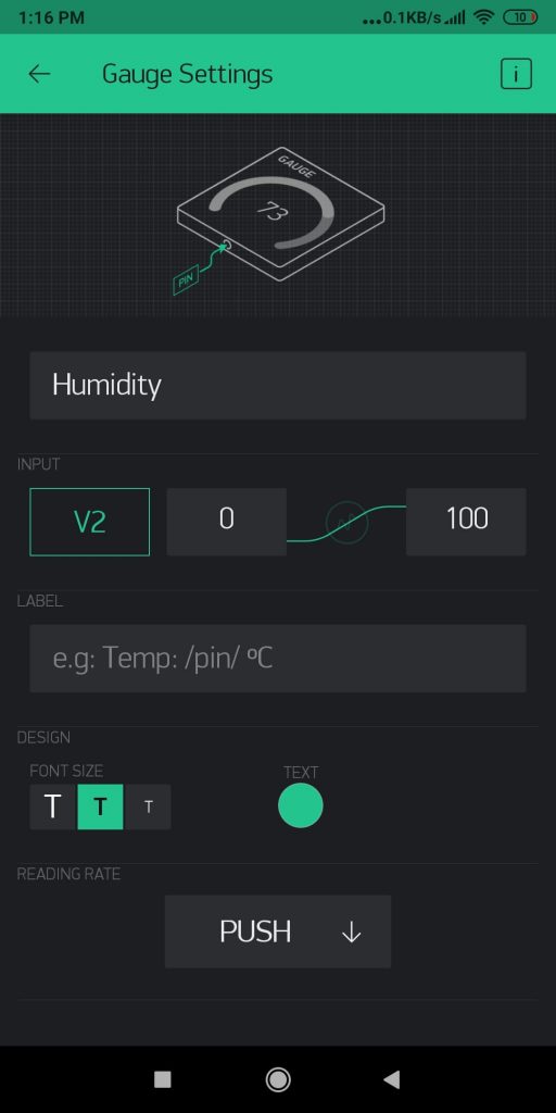
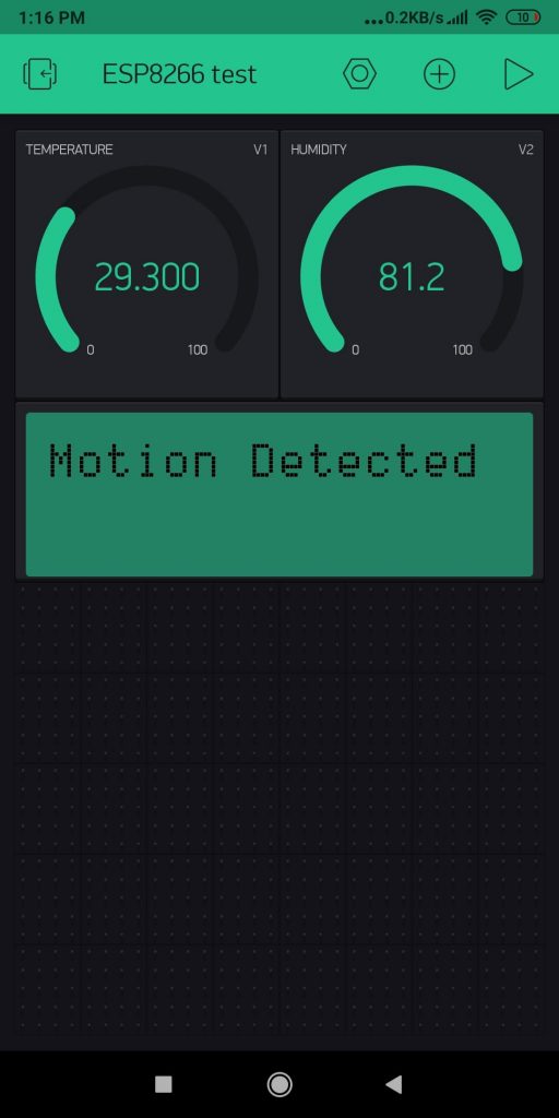
We need 2 display widgets for our DHT readings. Set them up as shown below. Be sure to set each widget to your desired virtual pin. In my case, I used V1 and V2. I set both to have a 0 minimum and 100 maximum value.
Below, you can set the update rate of the widget. I set mine to PUSH, meaning it updates as soon as my ESP8266 sends a data packet.
Your canvas should look like this. You can rearrange the order of the widgets by dragging and dropping them in position.
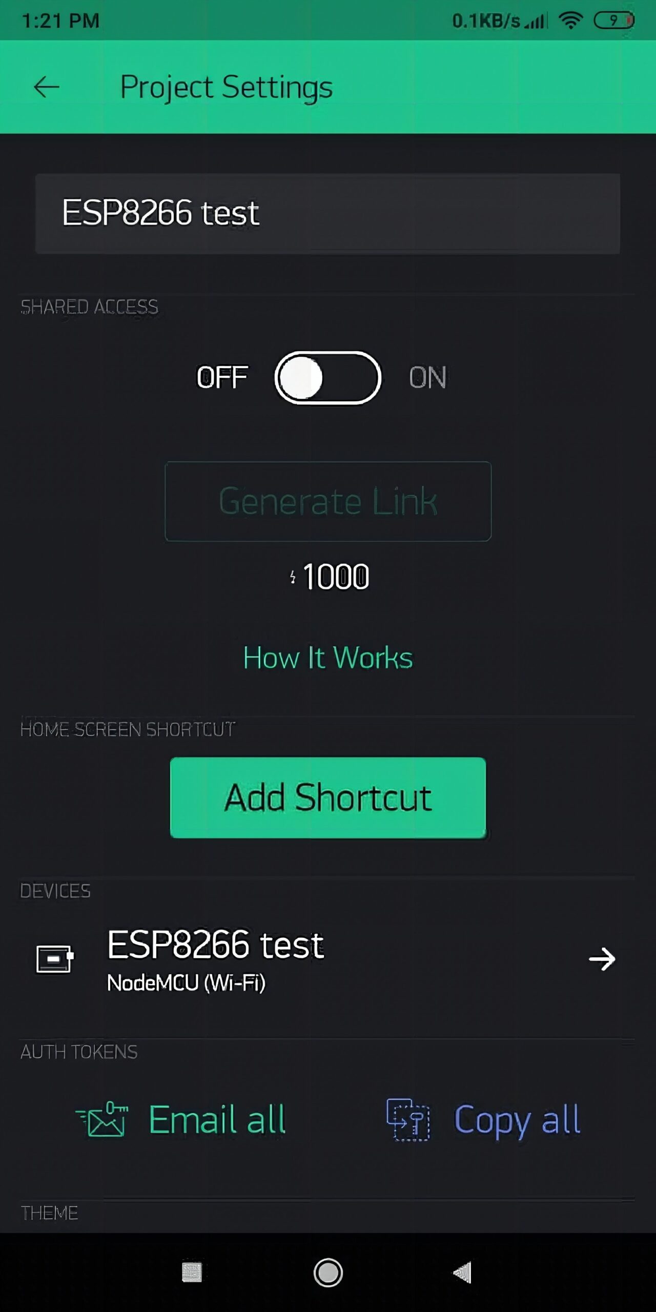
The top toolbar contains the project settings, add a widget, and run respectively. Project settings allow you to adjust and configure access control and acquire your authentication token. Add a Widget lets you add a widget as long as you have energy. Lastly, Run connects your dashboard to the server.
Inside project settings, click the email all button to receive an email containing your authentication token for this dashboard. Without the authentication token, Blynk won’t know what device to connect to your dashboard.
Code
#include <ESP8266WiFi.h>
#include <BlynkSimpleEsp8266.h>
#include <DHT.h> char auth[] = "Authentication Token";
char ssid[] = "Wifi Name";
char pass[] = "Wifi Password"; #define DHTPIN D5 #define DHTTYPE DHT22 DHT dht(DHTPIN, DHTTYPE);
BlynkTimer timer;
BlynkTimer timer1;
WidgetLCD lcd(V3); void readDHT()
{ float t = dht.readTemperature(); float h = dht.readHumidity(); Blynk.virtualWrite(V1, t); Blynk.virtualWrite(V2, h);
}
void detectMotion()
{ int motionstatus = digitalRead(D4); Serial.println(motionstatus); if (motionstatus == HIGH) { lcd.print(0,0,"Motion Detected"); } else if (motionstatus == LOW) { lcd.clear(); }
} void setup()
{ Serial.begin(9600); Blynk.begin(auth, ssid, pass); dht.begin(); timer.setInterval(1000L, readDHT); timer1.setInterval(1000L, detectMotion);
} void loop()
{ Blynk.run(); timer.run(); timer1.run();
}
Code Explanation
First, install the required libraries. You can either use the Arduino IDE’s library manager or get them here: Blynk, DHT. Concatenate strings to contain the authentication token, WiFi name, and password for ease of access. Then initialize them using Blynk.begin() and dht.Begin().
Next, set a DHT22 instance at pin D5. Create 2 timers for the DHT and PIR sensors so they can run simultaneously. Also, create a WidgetLCD connected to V3.
The functions readDHT() and detectMotion() are called by the 2 timers every 1000 milliseconds. readDHT() basically gets the temperature and humidity data from the DHT sensor and stores them into floats. Then, these floats are sent to the virtual pins using Blynk.virtualWrite(). On the other hand, detectMotion()constantly reads the digital signal from the PIR motion sensor. When it detects a HIGH, it sends an instruction to the LCD widget to display, “Motion Detected”.
Demonstration
Finally, to test the project, simply press Run.
Frequently Asked Questions
[faq] [faq_q]What is Blynk?[/faq_q] [faq_a]A mobile platform for IoT projects. You build a phone app from drag-and-drop widgets, link them to virtual pins on your microcontroller, and the Blynk cloud handles the connection.[/faq_a][faq_q]Is Blynk free?[/faq_q] [faq_a]Limited free tier with a quota of energy used per project. Paid plans for more widgets and devices. The article uses the free tier with a DHT-monitoring example.[/faq_a][faq_q]Does Blynk work without internet?[/faq_q] [faq_a]Blynk Edgent and the Blynk Local Server let you run the system on your local network. The standard Blynk app uses the cloud. The article uses cloud Blynk for simplicity.[/faq_a][faq_q]What sensors does the article use with Blynk?[/faq_q] [faq_a]A DHT22 temperature and humidity sensor wired to ESP8266. The Blynk app shows live readings on phone widgets.[/faq_a][faq_q]Can I use Blynk with Arduino instead of ESP8266?[/faq_q] [faq_a]Yes, but you need a network module (Ethernet shield or ESP8266 used as Wi-Fi adapter). The standalone ESP8266 with built-in Wi-Fi is simpler.[/faq_a][/faq]Frequently Asked Questions
What does this Blynk: Making Your Own Mobile Platform for ESP8266 tutorial cover?
In this tutorial, we are going to design a mobile platform that displays DHT data from an ESP8266 using the Blynk smartphone application.
Why won't my ESP8266 connect to home Wi-Fi?
ESP8266 only supports 2.4GHz. If your router is on 5GHz only, switch the SSID to a 2.4GHz band. Also check WPA2 (not WPA3) and that the SSID is broadcasting.
Should I use ESP8266 or ESP32 for the Blynk: Making Your Own Mobile Platform for ESP8266 build?
ESP8266 (NodeMCU/Wemos D1) is cheaper and fine for one Wi-Fi sensor + one I/O. ESP32 gives BLE, more GPIO, dual core, touch pins — pick it for richer projects.