
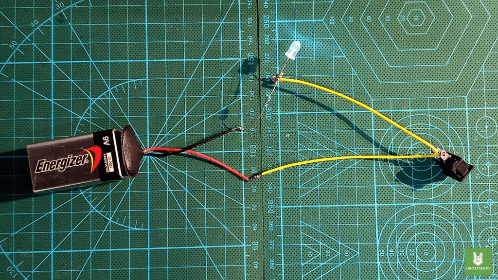
To try making a simple electronic circuit, you can connect an LED, a resistor, and a switch in a series. This setup is easy to assemble and teaches you how electrical components work together as a system. First and foremost, I want to highlight the LED which is an acronym for Light Emitting Diode. The LEDs are unique due to the fact that they only glow when an electric current passes through them, but the current must be in a certain direction – that is, from the positive end to the negative end.
A resistor reduces the amount of power flow, protecting the LED from receiving too much power. You determine the required resistance based on the battery’s power and the LED’s needs. Using this simple equation, you find that a 470ohm resistor will keep the LED safe and bright.
Last but not least, there is the switch that allows you to turn electricity on and off. When the switch is in the “on” position, it completes the circuit, the electricity flows from the battery, through the resistor, through the LED (lights it up), and back to the battery. When you flip the switch, it cuts the circuit, and electricity stops flowing to the LED bulb. This concept does not only demonstrate the way switches operate but also allows you to operate the circuit at your convenience.
Components
Remember
Soldering with lead-based solder gets easier with practice. Remember, safety first because lead is toxic. Always wash your hands after using lead-based solder and think about using lead-free solder if it works for your project.
QUICK LINKS
Frequently Asked Questions
What does this LED, Resistor, and Switch in Series: A Quick Guide tutorial cover?
To try making a simple electronic circuit, you can connect an LED, a resistor, and a switch in a series.
What's the working voltage of the LED, Resistor, and Switch in Series: A Quick Guide?
Check the Sample Code section for the exact pinout — most maker-grade sensors run on 3.3V or 5V. Wire VCC to the matching rail, GND common with your MCU, data to a digital or analog pin.
Why does the LED, Resistor, and Switch in Series: A Quick Guide read garbage or saturated values?
Three usual causes: wrong voltage rail, missing pull-up resistor on I2C lines (4.7k–10k to VCC), or a floating data pin. Double-check wiring against the diagram, then probe with a multimeter.