

In this tutorial, we are going to explore the pre-installed AT firmware inside the ESP8266.
The AT Firmware
The AT firmware is a pre-installed software in the ESP8266’s ROM (Read-Only Memory). It uses AT commands which are based on the Hayes Command Set. The Hayes Commands Set are commands for telecommunication operations. For instance, dialing a number or making a call.
Further, AT commands are often used for rapid testing of the ESP8266. They can either be sent using the serial monitor or via the ESP8266 sketch.
Sending AT commands using Arduino UNO
Parts you need:
- Arduino UNO
- ESP8266-01 module
- 1 x 1k? resistor
- 1 x 2.2k? resistor
- 1 x 10k? resistor
- Jumper wires
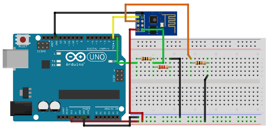
First, create a voltage divider using a 1k? and 2.2k? resistor. The default logic level of an Arduino is 5V. Although the ESP8266-01’s TX and RX pin are 5V tolerant, it still gets damage in the long run. To prevent this, we use a logic level converter or a voltage divider to reduce the signal to 3.3V. Next, initialize the ESP-01. Connect the EN/CH-PD (Enable) pin to the 3.3V supply. Use a 10k pull-up resistor.
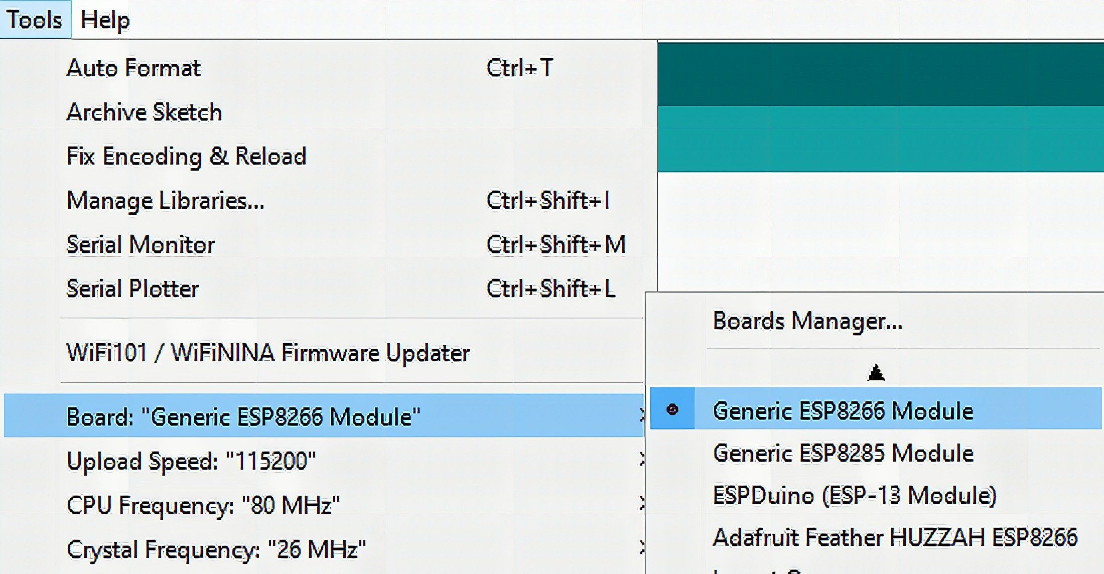
In the Arduino IDE, choose Generic ESP8266 Module as your board of choice.
Open the serial monitor. Set the baud rate to 115200 and enter the desired AT command.
Fundamental AT commands
AT+CWMODE
As mentioned in the previous article, the ESP8266 can be set to 3 different modes. To set the module as a station, enter AT+CWMODE=1. To set as an access point, enter AT+CWMODE=2. As both, enter AT+CWMODE=3. To check the current mode the ESP8266 is in, use AT+CWMODE?.
AT+CWLAP
See the available WiFi networks in your location.
AT+CWJAP="WiFi network name","Wifi network password"
Connect to a WiFi network.
AT+CIFSR
See ESP-01’s MAC and IP address.
AT+CIPMUX
Enable multiple connections using AT+CIPMUX=1. Disable it by using AT+CIPMUX=0.
AT+CIPSERVER
Start a server using AT+CIPSERVER=1,80. The first number indicates status. A value of 0 means closed while 1 means opened. The second number tells the port number.
AT+CIPSEND
Sends data to your server. To demonstrate, suppose you want to send 5 characters to channel 0. You should enter AT+CIPSEND=0,5 in the serial monitor.
The commands should look like this in the serial monitor.
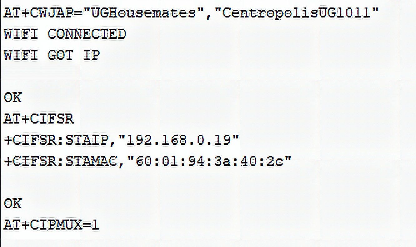
They are certainly easier to implement in the serial monitor than your usual Arduino framework.
See all 88 AT commands here.

But they have their limits. Let’s use them on actual Arduino code in the next section.
Using the Arduino to program the ESP-01
Parts you need:
- Arduino UNO
- ESP8266-01 module
- 1 x 1k? resistor
- 1 x 2.2k? resistor
- 1 x 10k? resistor
- Jumper wires

First, to set the Arduino board as an ESP programmer, connect the RESET pin to GROUND. Then, create a voltage divider just like before. Next, initialize the ESP-01. Connect the EN/CH-PD (Enable) pin to the 3.3V supply. Use a 10k pull-up resistor as well. Finally. connect the pin 0 to GND to start program mode.
In the Arduino IDE, choose Generic ESP8266 Module.
Using the NodeMCU
Parts you need:
- NodeMCU development board
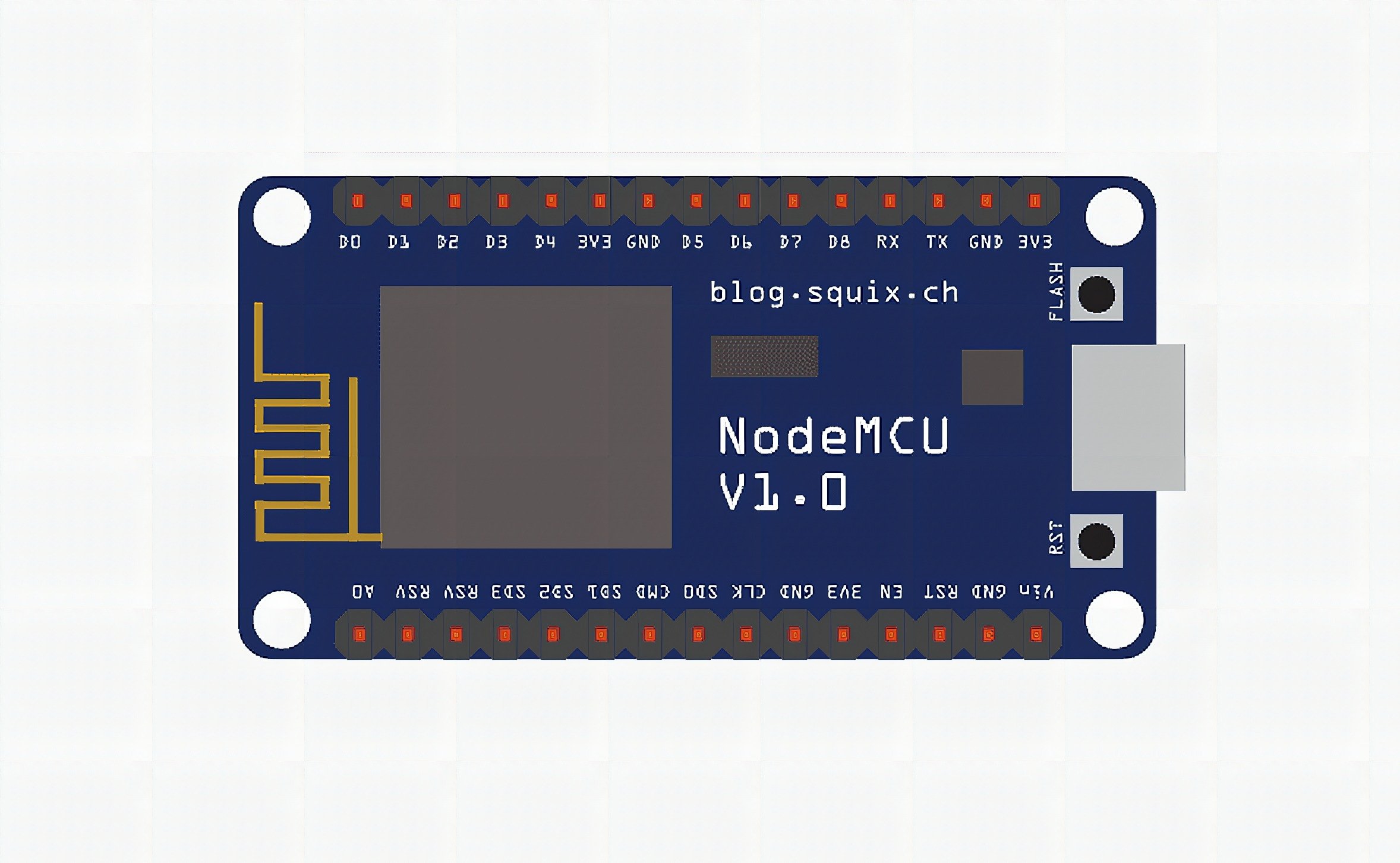
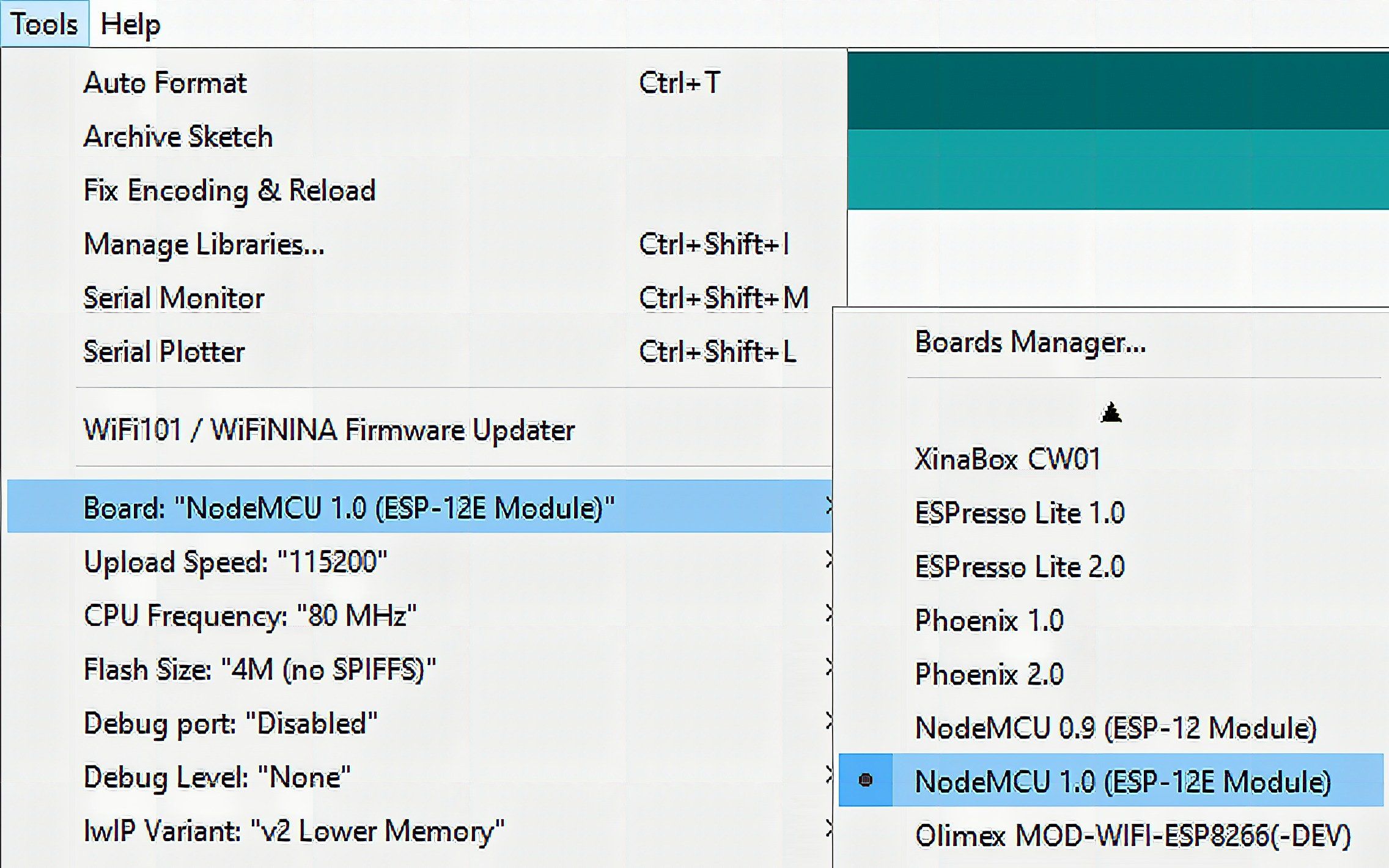
Plug and play! All you need to do is set the board in the Arduino IDE to NodeMCU.
Code
#include <SoftwareSerial.h> SoftwareSerial esp8266(2,3); #define serialCommunicationSpeed 115200 #define DEBUG true void setup() { Serial.begin(serialCommunicationSpeed); esp8266.begin(serialCommunicationSpeed); InitWifiModule(); } void loop() { if(esp8266.available()) { if(esp8266.find("+IPD,")) { delay(1000); int connectionId = esp8266.read()-48; String webpage = "<h1>Hello World!</h1>"; String cipSend = "AT+CIPSEND="; cipSend += connectionId; cipSend += ","; cipSend +=webpage.length(); cipSend +="rn"; sendData(cipSend,1000,DEBUG); sendData(webpage,1000,DEBUG); String closeCommand = "AT+CIPCLOSE="; closeCommand+=connectionId; // append connection id closeCommand+="rn"; sendData(closeCommand,3000,DEBUG); } }
} String sendData(String command, const int timeout, boolean debug)
{ String response = ""; esp8266.print(command); long int time = millis(); while( (time+timeout) > millis()) { while(esp8266.available()) { char c = esp8266.read(); response+=c; } } if(debug) { Serial.print(response); } return response; } void InitWifiModule()
{ sendData("AT+RSTrn", 2000, DEBUG); sendData("AT+CWJAP="SSID","Password"rn", 2000, DEBUG); delay (3000); sendData("AT+CWMODE=1rn", 1500, DEBUG); delay (1500); sendData("AT+CIFSRrn", 1500, DEBUG); delay (1500); sendData("AT+CIPMUX=1rn", 1500, DEBUG); delay (1500); sendData("AT+CIPSERVER=1,80rn", 1500, DEBUG); }
Code Explanation
First, initialize a SoftwareSerial communication line. The default pins for serial communication, 0 and 1, tend to get busy when the serial monitor is running. To avoid having corrupted data, we transfer serial communication with the ESP-01 to pins 2 and 3.
#include <SoftwareSerial.h> SoftwareSerial esp8266(2,3); Then, in the setup section, initialize the serial monitor and serial communications with your ESP8266’s baud rate. The default baud rate is 115200. Using InitWifiModule(), connect to your WiFi network.
void setup() { Serial.begin(serialCommunicationSpeed); esp8266.begin(serialCommunicationSpeed); InitWifiModule(); }Then, in the loop section, we store AT commands in strings so that we can send them via Software Serial. We use the sendData() to send them.
void loop() { if(esp8266.available()) { if(esp8266.find("+IPD,")) { delay(1000); int connectionId = esp8266.read()-48; String webpage = "<h1>Hello World!</h1>"; String cipSend = "AT+CIPSEND="; cipSend += connectionId; cipSend += ","; cipSend +=webpage.length(); cipSend +="rn"; sendData(cipSend,1000,DEBUG); sendData(webpage,1000,DEBUG); String closeCommand = "AT+CIPCLOSE="; closeCommand+=connectionId; closeCommand+="rn"; sendData(closeCommand,3000,DEBUG); } }
}
Demonstration
Upload the sketch to your ESP8266. Next, check for the serial monitor. It should display the IP address of your local webserver. Enter the IP address to your favorite browser.

Frequently Asked Questions
What does this Using AT commands on the ESP8266 tutorial cover?
In this tutorial, we are going to explore the pre-installed AT firmware inside the ESP8266.
Can I use an Arduino Nano or Mega instead of UNO for the Using AT commands on the ESP8266 build?
Yes. Nano shares the same ATmega328P and pinout. Mega has more I/O if you outgrow UNO. The code stays the same — just match the pin numbers used in the Sample Code section.
Why does my Using AT commands on the ESP8266 sketch fail to upload?
Usually wrong COM port, missing CH340/CH341 driver for clone boards, or another program holding the serial port. Disconnect the board, install the driver, reselect the port, retry.