
In this guide, I’ll show you how to build an ESP8266 Toggle Lock System. It lets you create a simple, remote-controlled lock for your door. For example, you can unlock or lock it with just the press of a button. As a result, it improves security and accessibility for homes and businesses.
In addition, the system uses basic electronic parts you can find easily. Because the ESP8266 can read button inputs and control outputs like relays and solenoids, you get a reliable locking solution. Moreover, you can integrate it with your existing door mechanism without much change.
We’ll use the Arduino IDE to program it. Therefore, it’s easy to write and upload the code. At the heart of the project, the ezButton library helps manage the button reliably. First, you’ll set up the button and relay in the code. Next, the relay will serve as the switch for the lock mechanism. Finally, when you press the button, the solenoid will move to lock or unlock the door. Because these steps are clear, even beginners can follow along.
Components
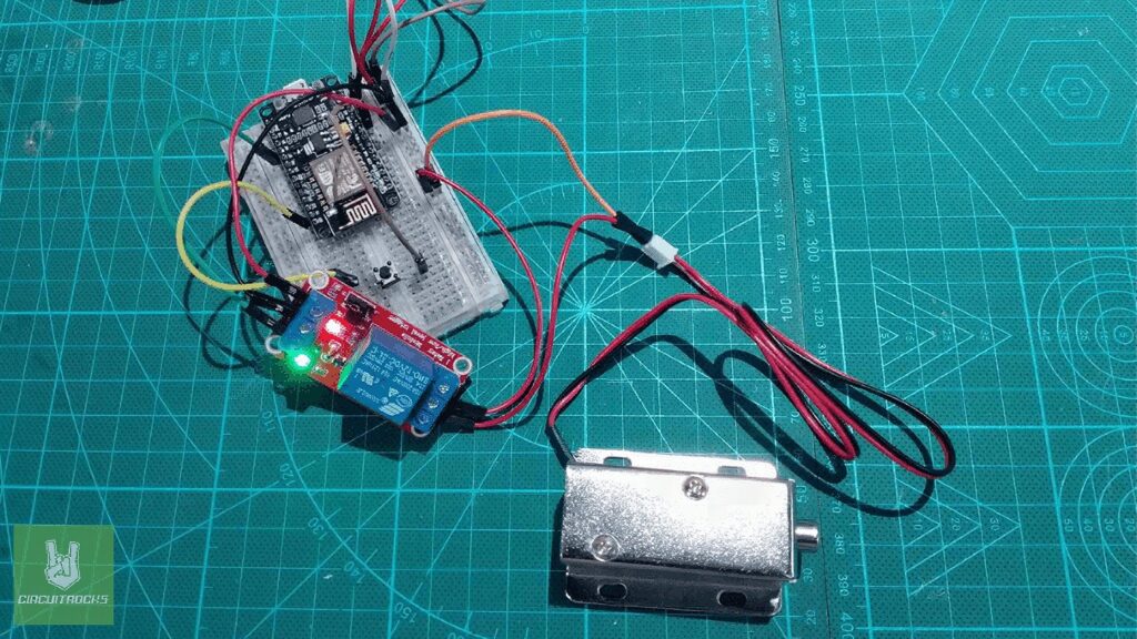
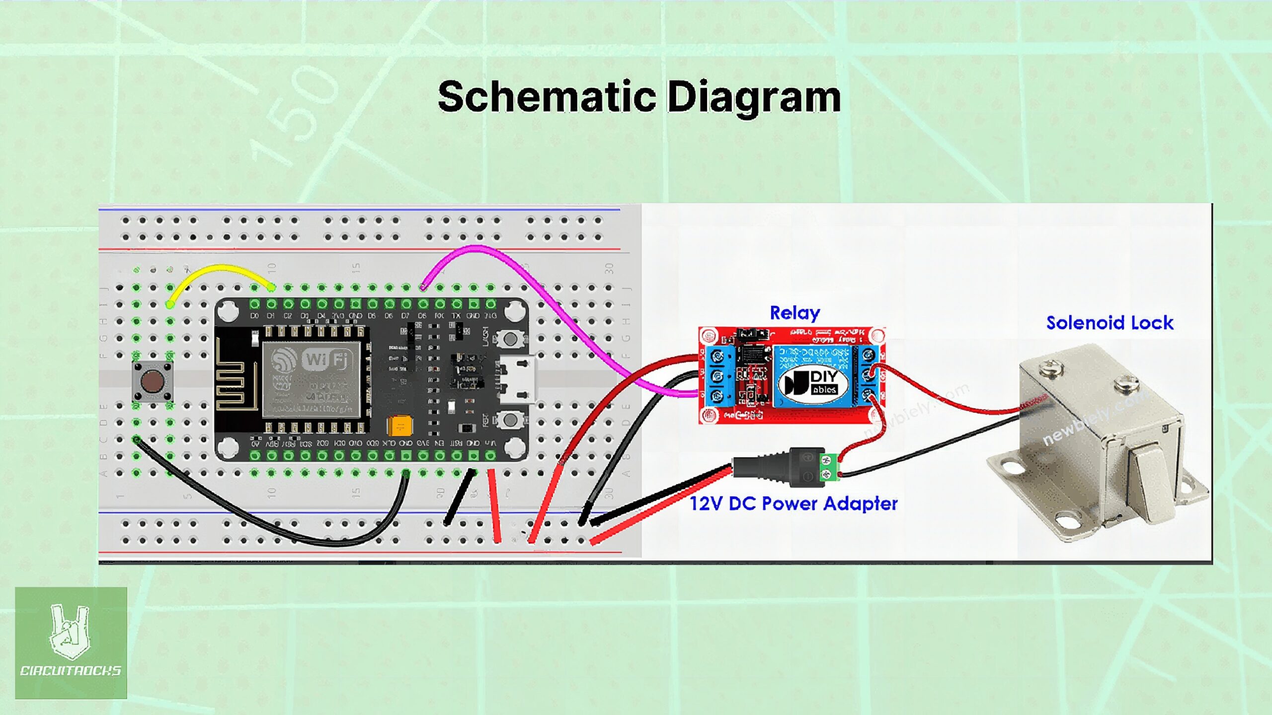
Connection:
Powering the Breadboard:
- Start with the Power Adapter 12V:
- Insert the Female Plug Adapter into the power supply.
- Next, Add Jumper Wires to the Breadboard:
- Attach the positive (red) jumper wire to the positive rail and the negative (black) jumper wire to the negative rail of the 400 Crystal Breadboard.
- Then, Wire the ESP8266 to the Breadboard:
- Connect the VIN pin to the positive rail and GND pin to the negative rail of the breadboard.
Setting Up the Relay:
- Power the Relay Module:
- Link DC+ (VCC) to the positive rail and DC− (GND) to the negative rail of the breadboard.
- Attach the IN pin of the relay to pin D8 on the ESP8266 v2.
Configuring the Tactile Button:
- Install the Tactile Button:
- Connect one side to pin D1 and the other side to GND on the ESP8266.
Connecting the Solenoid:
- Wire the Solenoid to Relay and Breadboard:
- Join the positive lead of the Solenoid Locked to the COM (common) terminal of the relay.
- Link the negative lead to the breadboard’s negative rail.
- Complete the Solenoid Circuit Through the Relay:
- Attach the NO (Normally Open) terminal of the relay to the positive rail of the breadboard.
Notes
Code:
This Arduino sketch is designed to control a lock (connected via a relay) using a button on an ESP8266 microcontroller. It uses the ezButton library to handle button inputs, which simplifies the process of debouncing the button. Debouncing is important as it ensures clean inputs are registered by the microcontroller. When the button is pressed, avoiding the false triggering that can occur due to the natural bouncing of electrical contacts when they close.
This code effectively creates a simple locking system where pressing a button toggles the lock state and the current state is indicated both by the relay’s output.
#include <ezButton.h> #define BUTTON_PIN D1 // The ESP8266 pin connected to the button's pin
#define RELAY_PIN D8 // The ESP8266 pin connected to the relay's pin ezButton button(BUTTON_PIN); // create ezButton object for pin D1
bool locked = true; // Boolean to keep track of lock state void setup() { Serial.begin(9600); // Initialize the Serial to communicate with the Serial Monitor. pinMode(RELAY_PIN, OUTPUT); // Set ESP8266 pin to output mode button.setDebounceTime(50); // Set debounce time to 50 milliseconds digitalWrite(RELAY_PIN, HIGH); // Initially lock the door
} void loop() { button.loop(); // MUST call the loop() function first if(button.isPressed()) { locked =!locked; // Toggle the lock state if (locked) { Serial.println("The door is locked"); digitalWrite(RELAY_PIN, HIGH); // Lock the door } else { Serial.println("The door is unlocked"); digitalWrite(RELAY_PIN, LOW); // Unlock the door } }
}
Troubleshooting:
- Component Isolation: Test each component independently to isolate the faulty part. This could involve swapping components like the relay or ESP8266 with known good units.
- Connection Check: Make sure the solenoid’s connections to the relay and power supply are secure.
- Reset and Reboot: Sometimes, simply resetting or rebooting the ESP8266 can resolve transient issues.
- Serial Output: Check the serial monitor to see if the button press is being detected and is toggling the lock state variable.
- Physical Inspection: Listen for a clicking sound from the relay when activated; absence of this sound could indicate a malfunction.
QUICK LINKS
Frequently Asked Questions
What does this ESP8266 Toggle Lock System tutorial cover?
In this guide, I’ll show you how to build an ESP8266 Toggle Lock System.
Why won't my ESP8266 connect to home Wi-Fi?
ESP8266 only supports 2.4GHz. If your router is on 5GHz only, switch the SSID to a 2.4GHz band. Also check WPA2 (not WPA3) and that the SSID is broadcasting.
Should I use ESP8266 or ESP32 for the ESP8266 Toggle Lock System build?
ESP8266 (NodeMCU/Wemos D1) is cheaper and fine for one Wi-Fi sensor + one I/O. ESP32 gives BLE, more GPIO, dual core, touch pins — pick it for richer projects.