
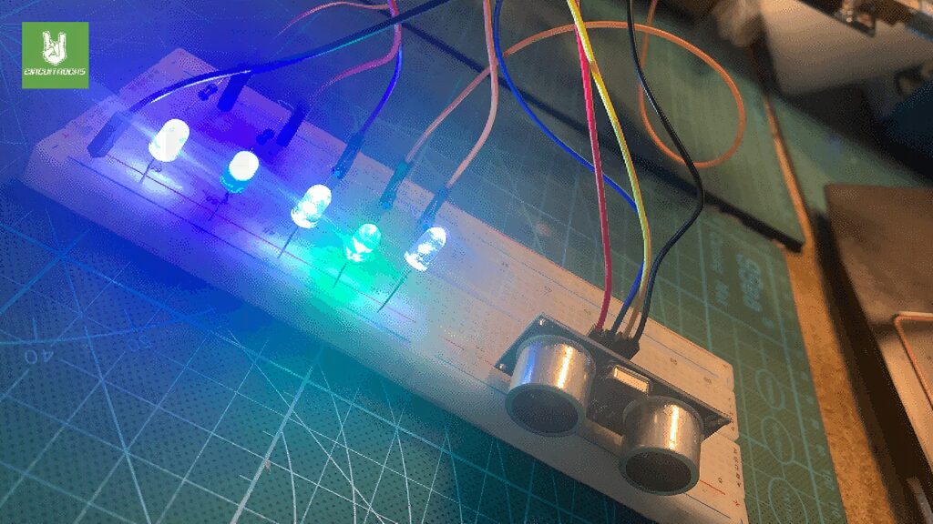
The Arduino Ultrasonic Sensor with LED Indicators project is a simple and creative way to blend ultrasonic distance measurement with LED technology. For example, it uses an HC-SR04 ultrasonic sensor to detect how close an object is. In addition, when something approaches, the sensor measures the distance and triggers LEDs to light up. As a result, this setup offers an easy and fun introduction to Internet of Things applications.
This project is perfect for beginners who want hands-on experience with Arduino. First, it shows how sensors can detect movement or distance. Next, it teaches how to control LEDs based on sensor input. Moreover, it helps users understand basic coding and wiring. Because these elements work together, learners can see real-time responses as the LEDs react to the detected distance.
Finally, developing LED systems like this has benefits beyond simple projects. For instance, such technology can improve safety by providing clear signals when something is too close. Therefore, it can be used in cars, factories, or smart homes. Because it is affordable and easy to build, this project is a great starting point for anyone exploring electronics, while showing how innovation can lead to better, more efficient solutions for the future.
Components
Connections

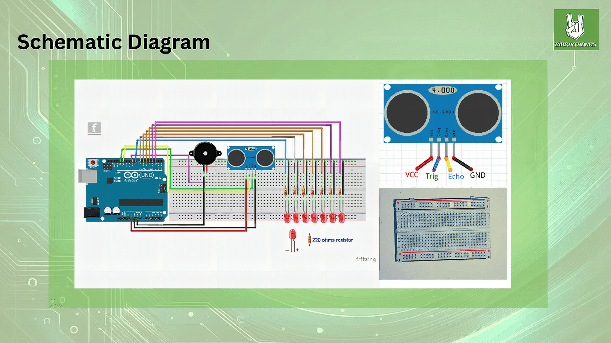
Ultrasonic Sensor HC-SR04
- VCC to Arduino 5V.
- GND to Arduino GND.
- Trig to pin 12.
- Echo to pin 13.
LEDs with 220-Ohm Resistors
- Each LED’s anode (longer leg) connects to its corresponding Arduino pin (2 to 6 for
LED1toLED5). - Connect a 220-ohm resistor in series with each LED’s cathode (shorter leg), and then connect the other end of the resistor to the Arduino’s GND.
Breadboard
- Use the breadboard to make the connections easier and more organized, especially for the resistors and LED connections. Place the resistors and LEDs on the breadboard, and use jumper wires to connect them to the Arduino pins and GND.
Code:
const int echo = 13;
const int trig = 12; int duration = 0; int distance = 0; void setup() { pinMode (trig, OUTPUT); pinMode (echo, INPUT); pinMode (LED1,OUTPUT); pinMode (LED2,OUTPUT); pinMode (LED3,OUTPUT); pinMode (LED4,OUTPUT); pinMode (LED5,OUTPUT); Serial.begin(9600);
} void loop() { digitalWrite(trig, HIGH); delayMicroseconds(1000); digitalWrite(trig, LOW); duration = pulsein(echo, HIGH); distance = duration/2) / 28.5; Serial.printin(distance); if ( distance <=7 ) { digitalWrite (LED1, HIGH); } else { digitalWrite (LED1, LOW); } if ( distance <=14 ) { digitalWrite (LED2, HIGH); } else { digitalWrite (LED2, LOW); } if ( distance <=21 ) { digitalWrite (LED3, HIGH); } else { digitalWrite (LED3, LOW); } if ( distance <=28 ) { digitalWrite (LED4, HIGH); } else { digitalWrite (LED4, LOW); } if ( distance <=35 ) { digitalWrite (LED4, HIGH); } else { digitalWrite (LED4, LOW); }
}
Troubleshooting
- Ensure Correct Function Names: Use
pulseIn(capital ‘I’) andSerial.println(notprintin) for correct syntax. - Correct Calculation: Use
29.1as the divisor when converting duration to distance in centimeters, assuming air temperature around 20°C. This factor might need adjustment for precise applications or different conditions. - LEDs Not Lighting Up: Verify all LEDs are connected correctly with their anodes to the specified pins and cathodes to GND. Use resistors (220Ω) in series with each LED to limit current.
QUICK LINKS:
Frequently Asked Questions
What does this Arduino Ultrasonic Sensor with LED Indicators tutorial cover?
The Arduino Ultrasonic Sensor with LED Indicators project is a simple and creative way to blend ultrasonic distance measurement with LED technology.
What Arduino library does the Arduino Ultrasonic Sensor with LED Indicators tutorial use?
The sketch uses standard Wire.h (I2C) or SPI.h plus a part-specific library installable via Arduino IDE → Sketch → Include Library → Manage Libraries. See the Sample Code section.
Why does the Arduino Ultrasonic Sensor with LED Indicators act differently on USB power vs battery?
Battery voltage sags under load. Add a 100uF cap across the rails, use a 5V/2A regulator-backed pack, and never power motors from the Arduino's onboard regulator.