


One of the most exciting projects with an Arduino is giving the project its own eyes, so to speak. Adding a camera to an Arduino project opens up a broad list of applications, such as monitoring and surveillance systems. In this Learn article, we will be introducing the OV7670 VGA camera, showing how to interface the module with an Arduino Uno, and demonstrating how to open the captured image.
Wiring Diagram
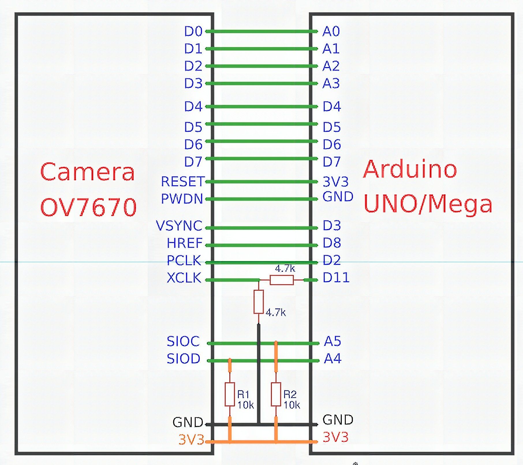
And with that, we are ready to test out the camera.
Programming Arduino Uno
When programming the Arduino Uno to interface with the OV7670 Camera, we first have to include a couple of libraries. The OV7670 Camera utilizes an I2C interface, which means the library is needed. Here is the list of libraries required:
- <stdint.h>
- <avr/io.h>
- <util/twi.h>
- <util/delay.h>
- <avr/pgmspace.h>
Some of the important functions in the code are:
- arduinoUnoInut(); // Placed in Setup(), this function initializes the Arduino Uno
- setResolution(); // Selects the resolution for the QVGA image that will be taken
- setColor(); // sets the register values that would be used to define the color mode.
- writeReg(0x11, 10); // the write-to-register function, which is in hex values.
- captureImg(320, 240); // Function to get the image resolution size.
To download the sample code, click here.
Compile and upload the code to the Arduino Uno.
Serial Port Reader
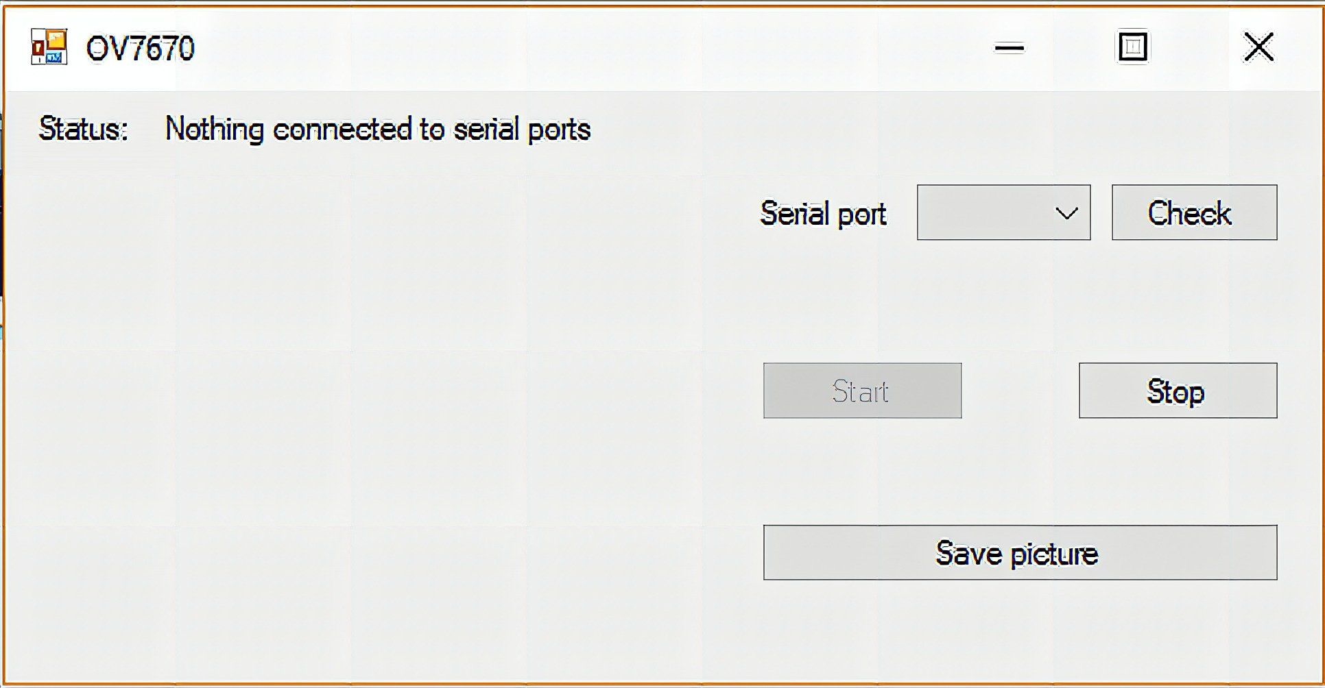
Lastly, we need to be able to fetch the data and display it. We need to use a simple GUI called Serial Port Reader to do this. You can download the file here. Run the file and follow the steps below.
1. Run Serial Port Reader
2. Connect the Arduino Uno to the PC via USB Port and select the Serial port that the Arduino is designated in.
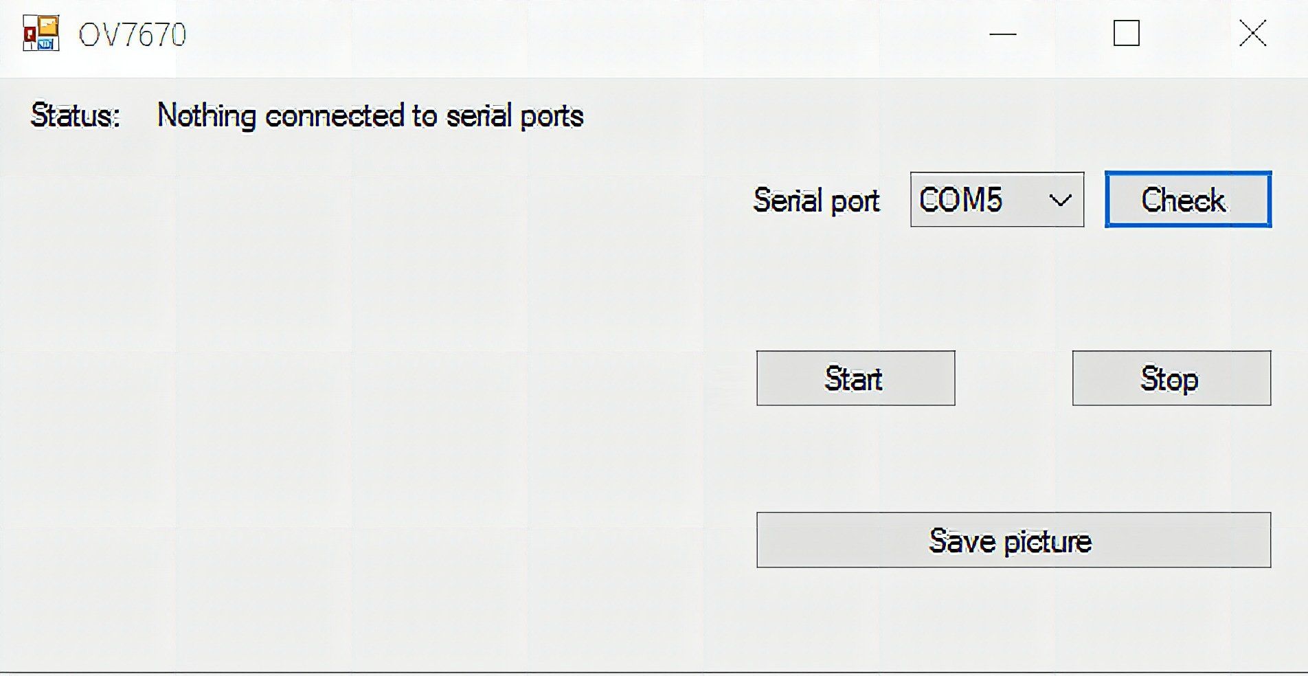
3. Click on “Start” to begin serial read.
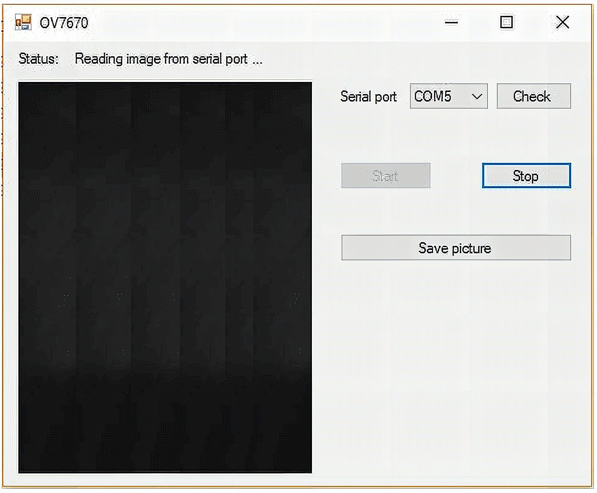
4. Save images by clicking on “Save picture”.
Frequently Asked Questions
What does this Getting Started With the OV7670 Camera for Arduino tutorial cover?
One of the most exciting projects with an Arduino is giving the project its own eyes, so to speak.
Can I use an Arduino Nano or Mega instead of UNO for the Getting Started With the OV7670 Camera for Arduino build?
Yes. Nano shares the same ATmega328P and pinout. Mega has more I/O if you outgrow UNO. The code stays the same — just match the pin numbers used in the Sample Code section.
Why does my Getting Started With the OV7670 Camera for Arduino sketch fail to upload?
Usually wrong COM port, missing CH340/CH341 driver for clone boards, or another program holding the serial port. Disconnect the board, install the driver, reselect the port, retry.