

Resistors are an omnipresent component on every electronic circuit. Today, we get to learn more about them, their different types, applications, and proper usage.
What is a Resistor?
A resistor is an electronic component with a fixed resistance value. Moreover, they are passive components, which means they cannot produce energy. They are often added to circuits to lessen current flow to a value safe for an active component.
Resistors appear like this on schematics:

Types of Resistors
Through Hole
Through-hole resistors are the first pick in Arduino craft. These resistors are what we use in prototyping since they fit right into a breadboard. They kind of look like skewers because of their long legs.
Also, they are popular with Printed Circuit Boards. These resistors are easy to solder. You can always cut their legs to fit into your designs.

Through-Hole Resistor (Image Credit: Adafruit)
The size of a through-hole resistor indicates its power rating. The larger the resistor is, the higher its power capabilities. Also, take note that a higher power rating means that the resistor won’t heat up easily. Further, the resistance value is printed on the resistors’ body using this color coding.
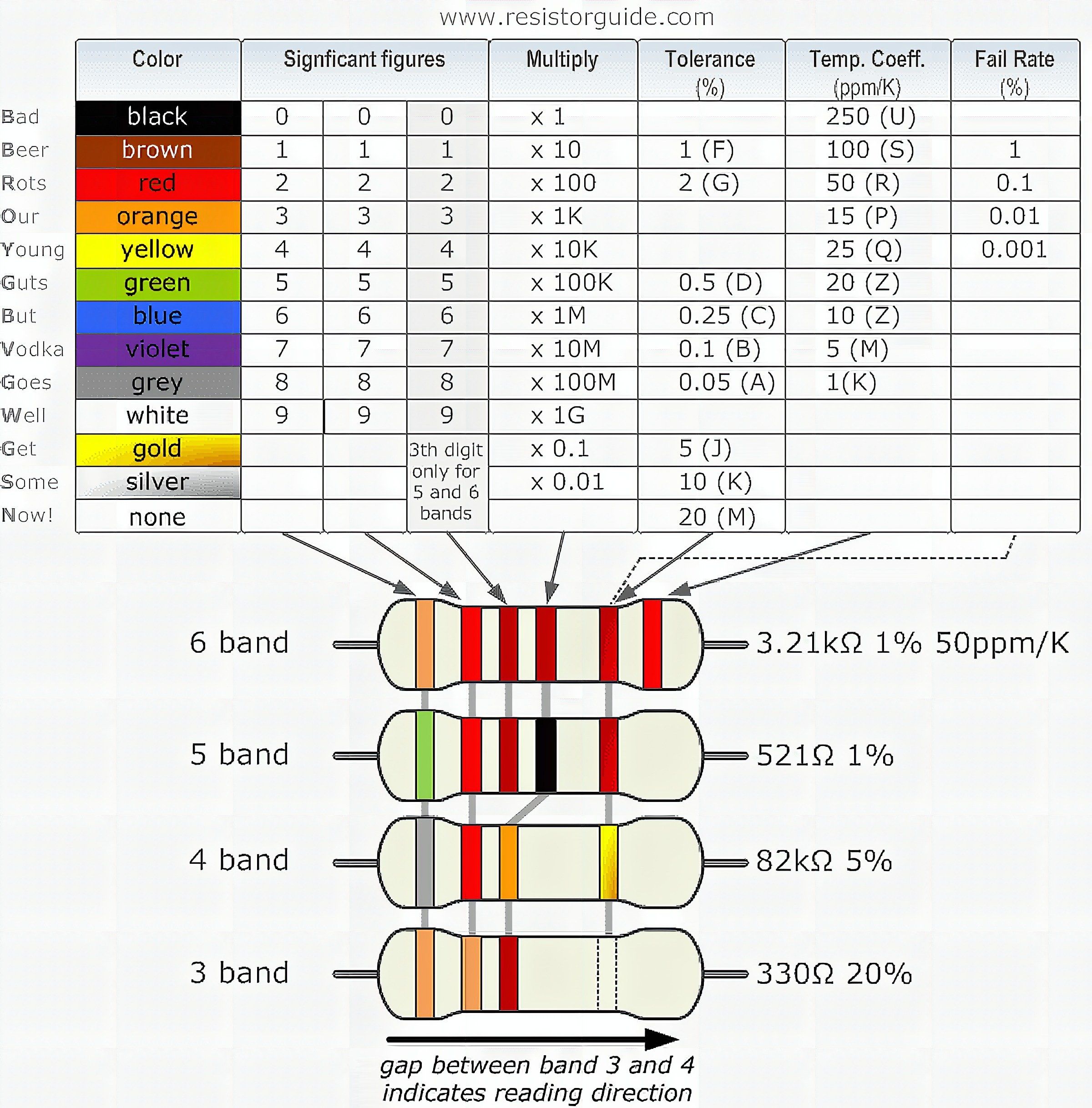
Resistor color code (Image credit: Resistor guide)
This color-coding is defined by the international standard IEC60062. Apart from indicating electric resistance, this code also determines the resistor’s tolerance and failure rating. Normally, the first three bands indicate the resistance value while the remaining shows the tolerance and failure rating respectively.
The color code is indeed very helpful but if you’re still doubtful, you can always use an ohmmeter. Since resistors have no polarity, just put the tester leads on the resistor’s two legs and you are going to get its rating.
Surface Mount
On the other hand, surface-mount resistors are like tiny chocolate bars. You can find them on top of PCBs. If you have an Arduino, you can see them in line like this.
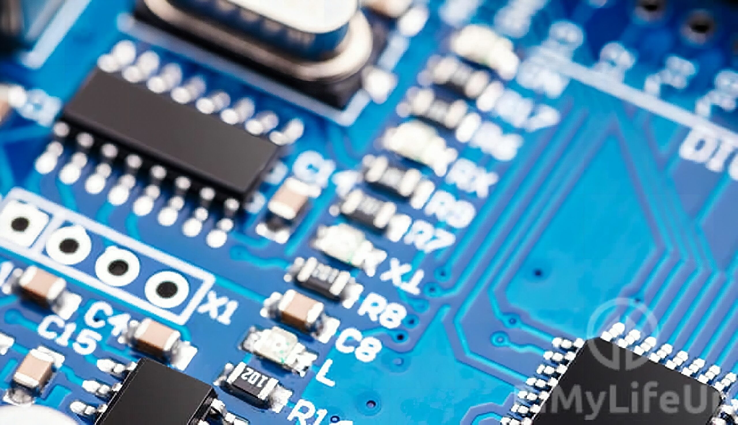
SMD resistors (Image Credit: PiMyLifeUp)
These resistors are normally used in professionally manufactured PCBs since they are significantly harder to solder than through-hole resistors.
The resistance value of an SMD appears as characters marked on the resistor. These characters use coding systems with some more obscure than the other.
If all characters are numbers, that is an E24 code. You can read it similar to the color bands of through-holes. The first two or three numbers indicate the value while the last one determines the multiplier. For instance, take this resistor below.
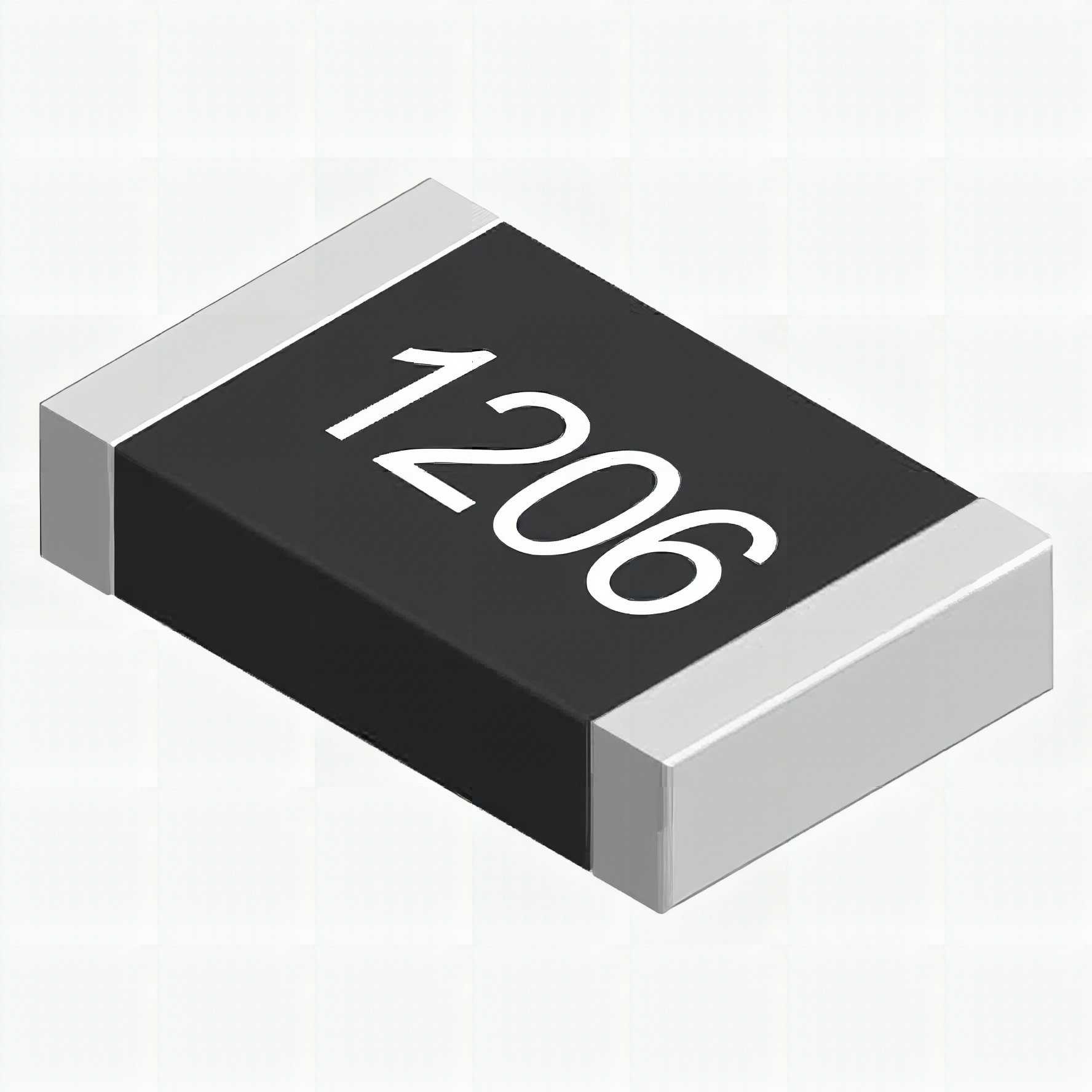
Take the first three numbers 120 and multiply it with 10 raised to 6. You are going to get 12,000,000. That means this resistor has an electric resistance of 12M?.
Interestingly, Arduino development boards use SMD resistors with E24 codes.
Potentiometers
Potentiometers are variable resistors. This means that you can adjust its electric resistance to the value you desire. This may sound unfaithful to the definition of resistors above but, the resistance value of the potentiometer remains fixed when left alone.
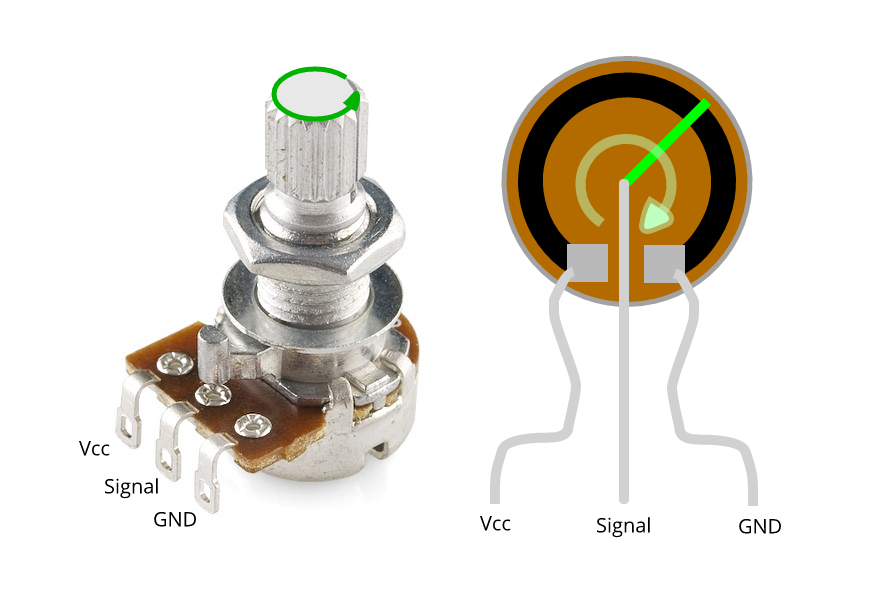
Potentiometer (Image Credit: Core-electronics)
The value of a potentiometer is written on the back of the knob. For instance, a 10K marking on a potentiometer means its maximum resistance value is 10,000?. You can use the potentiometer as a variable voltage divider by connecting the three terminals. Alternatively, you can use it as a variable resistor or a rheostat by connecting two adjacent terminals.
Potentiometers are usually seen on LCD modules as a manual adjust parameter for screen to print contrast.
Uses of a Resistor
Current Limiter
Perhaps the most common use of a resistor in any circuit is to limit current flow. Using the Ohm’s Law we discussed in the previous article, we can compute for the needed resistor for an electronic component.
To demonstrate, suppose we have an LED with a 20mA current rating. This LED has a forward voltage of 2.8V. To achieve that current with a 5V power supply, we are going to divide the difference of 5 and 2.8V by 0.02A. That gives us 110?. You should add a resistor that has 100? or higher resistance value to prevent your LED from burning.
Bleeder Resistor
A bleeder resistor is a resistor in parallel with the output of an electronic device. They are used to soften up discharges from capacitors. Mostly, they are used in sensitive electronics.
Voltage Divider
Resistors can be used as a voltage divider as well. A voltage divider, as the name implies, turns a large voltage into a smaller one. It’s like a faux transformer. A voltage divider circuit consists of two resistors in series. It looks like this.
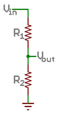
The output voltage can be computed as:

Pull-up and Pull-down Resistor
Finally, pull-up and pull-down resistors are resistors you add to a microcontroller’s input pin to stabilize the digital signal incoming. Without a pull-up or pull-down resistor, a microcontroller pin floats. This means it is on a state that fluctuates randomly to a LOW or HIGH.
Adding a pull-up resistor makes the pin stay on HIGH while a pull-down makes it stay on LOW. This is very helpful for development boards like an Arduino, especially when interfacing with switches.
That’s it for resistors. Hope you learned something new. Check this article for the first part of the basic electronics series. See you later!
Frequently Asked Questions
What does this Basic Electronics: Resistors tutorial cover?
Resistors are an omnipresent component on every electronic circuit.
What's the working voltage of the Basic Electronics: Resistors?
Check the Sample Code section for the exact pinout — most maker-grade sensors run on 3.3V or 5V. Wire VCC to the matching rail, GND common with your MCU, data to a digital or analog pin.
Why does the Basic Electronics: Resistors read garbage or saturated values?
Three usual causes: wrong voltage rail, missing pull-up resistor on I2C lines (4.7k–10k to VCC), or a floating data pin. Double-check wiring against the diagram, then probe with a multimeter.