
We’ve already covered wireless technologies and UART. This time we’re looking at Inter-Integrated Circuits, or I2C.
I2C
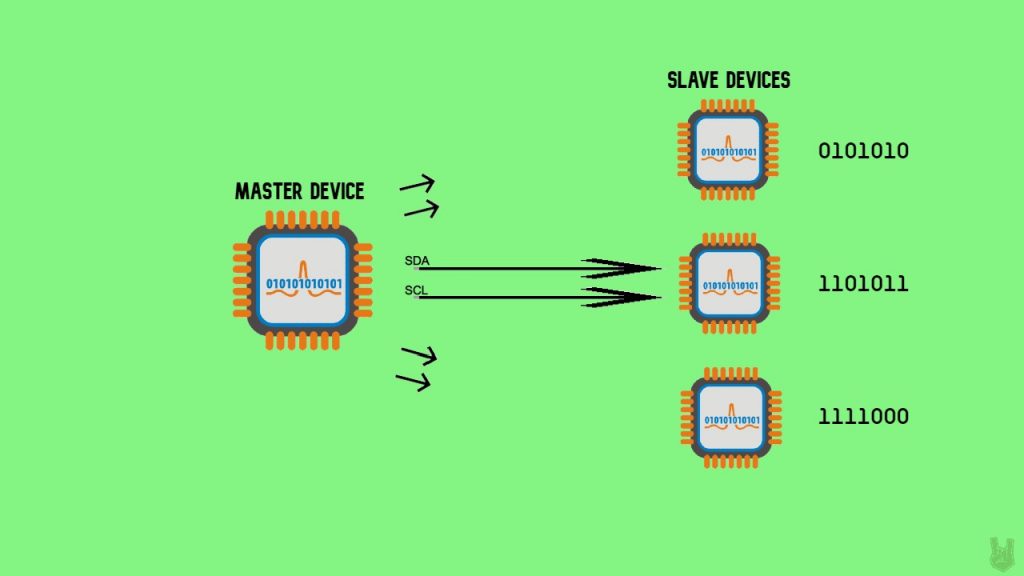
I2C (Inter-Integrated Circuits) is a serial communication protocol that connects multiple slaves to a single master and vice versa. That’s handy when you’ve got a bunch of peripheral devices all logging data into one microcontroller. And like UART, it only needs two wires. Those two wires are:
SDA (Serial Data Line) – This line is where the master and slave devices communicate.
SCL (Serial Clock Line) – This line synchronizes the devices. It carries the clock signal.
I2C is synchronous, so it needs a clock signal. Want a refresher on synchronous vs asynchronous communication? Check the previous article.
Anatomy of an I2C message
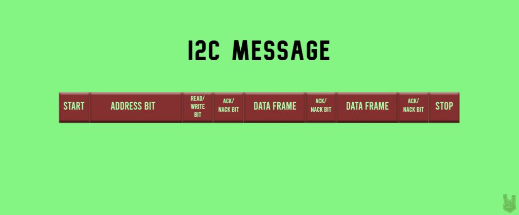
Start Condition: A start bit is a LOW added to the beginning of a data packet to kick off the transfer. In I2C, to start the message, the SDA line drops from a HIGH to LOW before the SCL line switches from HIGH to LOW.
Stop Condition: A stop bit pulls the digital signal to HIGH for at least two-bit durations to mark the end of the transmission. The SDA line rises from LOW to HIGH after the SCL line switches from LOW to HIGH.
Address Frame: A series of 7 or 10 bits distinct to every master or slave device.
Read/Write Bit: This bit says whether the master is sending data (LOW) or requesting it (HIGH).
ACK/NACK Bit: ACK/NACK is short for Acknowledge and No-Acknowledge bits. A receiving device returns an ACK if the data arrived without errors. If the message is corrupted or incomplete, the receiving device sends a NACK instead.
How I2C Works
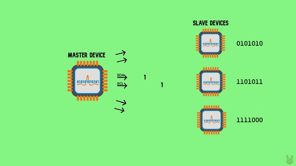
1. The master starts the start condition by dropping the SDA signal to LOW, followed by the SCL.

2. The master sends every slave a 7 or 10 address bit to pick out the target slave for communication. Then it sends a read or write bit.
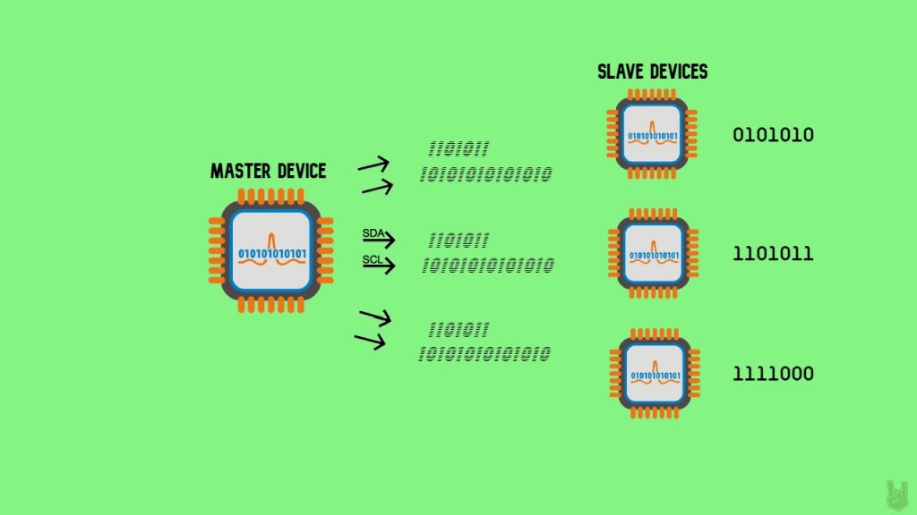
3. Each slave compares the address bit sent by the master to its own address. If the address matches, it returns an ACK by dropping the SDA signal LOW for a moment.
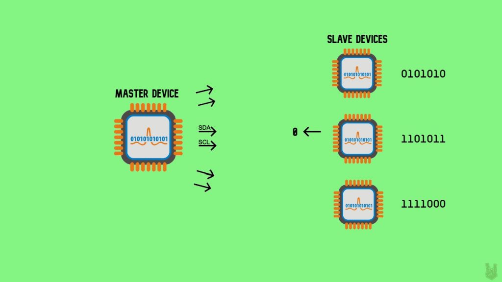
4. The master communicates with the target slave.
5. Once all the data has been sent, the slave returns an ACK to let the master know the message came through fine.

6. To end the communication between the master and the target slave, the master triggers the stop condition. It returns both the SDA and SCL lines to HIGH, doing the SCL first then the SDA.
Advantages
- Requires only 2 lines of communication
- It can support multiple masters and slaves
- Chip addressing
- Simpler than UART
Disadvantages
- Slow data rate
- Requires more space
- Conflicts may arise because of chip addressing
So that’s I2C. It’s a solid pick for driving peripheral devices since it handles multiple master and slave devices, and like UART it only needs two lines to talk.
Here are the default I2C lines on different Arduino boards:
Uno, Ethernet?:?A4 (SDA), A5 (SCL)
Leonardo?:?2 (SDA), 3 (SCL)
Due?:?20 (SDA), 21 (SCL), SDA1, SCL1
Mega2560?:?20 (SDA), 21 (SCL)
That’s it for I2C! Hope to see you at the final one!
Frequently Asked Questions
What does this Wired Communication Protocols: I2C tutorial cover?
So far we’ve talked about wireless technologies and UART communications.
What's the working voltage of the Wired Communication Protocols: I2C?
Check the Sample Code section for the exact pinout — most maker-grade sensors run on 3.3V or 5V. Wire VCC to the matching rail, GND common with your MCU, data to a digital or analog pin.
Why does the Wired Communication Protocols: I2C read garbage or saturated values?
Three usual causes: wrong voltage rail, missing pull-up resistor on I2C lines (4.7k–10k to VCC), or a floating data pin. Double-check wiring against the diagram, then probe with a multimeter.