

In this new series of articles, we are going to explore wired communication protocols. It will consist of 3 parts, starting with this one for UART.
Introduction
Wired communication protocols are essential to Arduino. In fact, as I mentioned before, you need it to send a program or else your Arduino remains blank.
These wired protocols, along with the wireless tech we have discussed, can be classified into two categories:
- Serial
- Parallel
Serial communication sends data one bit at a time while parallel communication transmits bits simultaneously. Undoubtedly, parallel communication is faster. The only drawback is that it uses a lot of communication channels. On the other hand, serial communication only needs at least two channels to function. This is a significant detail for Arduino since its pins are limited. Furthermore, parallel becomes unreliable when used at greater distances. With this, it is almost imperative for the Arduino to use serial communication to talk to external devices. This is why the majority of wired communication protocols it supports are serial.
The following are the Arduino standard wired communication protocols:
- UART
- I2C
- SPI
UART
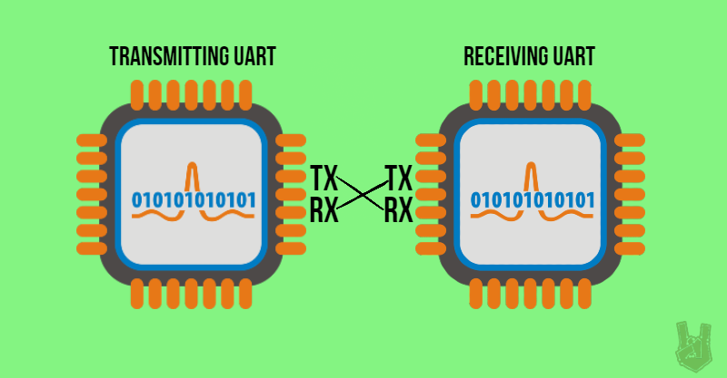
UART (Universal Asynchronous Receiver/Transmitter) is actually hardware. It is a circuit inside a microcontroller that enables serial communication. It allows the board to receive and transmit data using only two connections.
UARTs communicate by converting parallel data from a microcontroller to serial. Then, a receiver UART takes the serial data and converts it to parallel for its own microcontroller. The data exchange occurs from the Tx pin of the transmitter UART to the Rx pin of the receiver UART.
Synchronous and Asynchronous Transmission
Synchronous and Asynchronous transmissions are communication techniques that synchronize data exchange between two devices. Without these two, transmitted data cannot be read properly. To demonstrate, suppose you send a “Hello” message. Without synchronizing, you are going to get misordered words like “oHell” or “lloHe”.
Furthermore, Synchronous transmission uses an external clock while Asynchronous transmission uses special markers that indicate the start and end of a message.
UART uses Asynchronous transmission. The transmitting UART uses start and stop bits to mark the start and end of a data packet. When a receiving UART detects a start bit, it reads the following bits in a specific frequency called baud rate.
How UART works
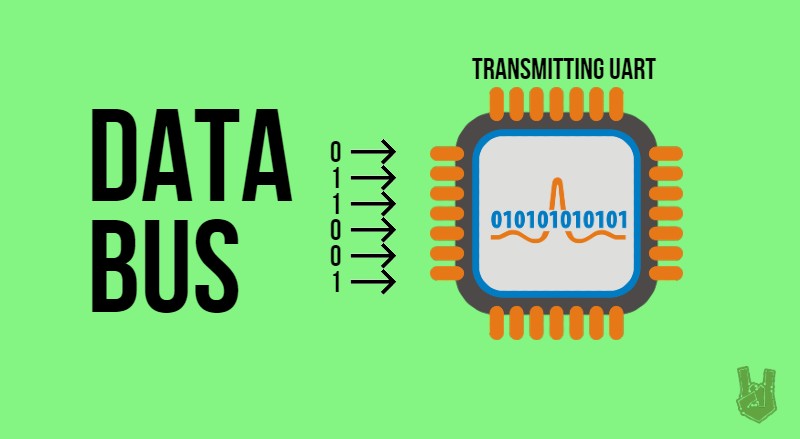
1. First, a transmitting UART receives data in parallel from a microcontroller’s data bus.
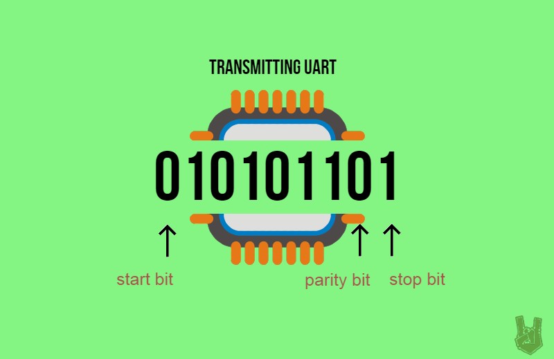
2. After that, the transmitting UART adds a start bit, a parity bit, and a stop bit to the data packet. A UART Tx pin is normally HIGH when inactive.
A start bit is a LOW added to the beginning of a data packet to initiate data transfer.
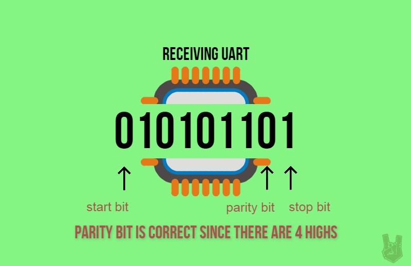
A parity bit is a communication technique used to check for transmission errors. It counts the number of HIGHs in the data frame. For example, if there are two HIGHs, the parity bit is 0 (Even Parity). Whereas, if there are three HIGHs, the parity bit is 1 (Odd Parity). If the receiving UART sees three HIGHs but the parity bit is 0, it counts the message as an error and request for retransmission.
A stop bit pulls the digital signal to HIGH for at least two-bit durations to indicate the end of the transmission.
3. Then, the entire data packet is sent to the receiving UART in series. The receiving UART samples the message in the specified baud rate.
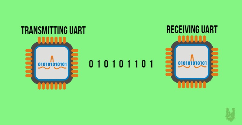
4. At this time, the receiving UART decodes the message by analyzing the added bits.
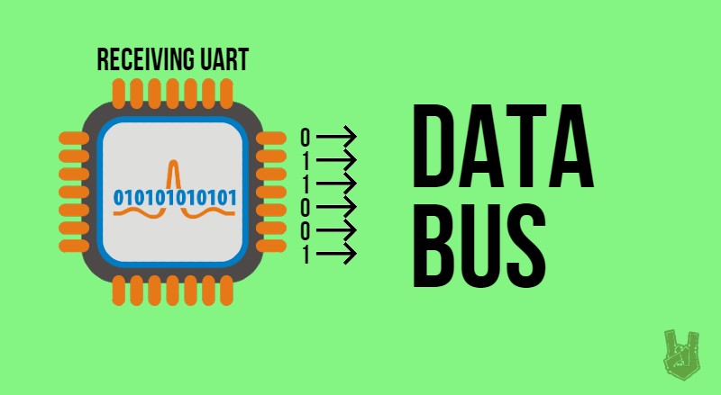
5. Finally, the receiving UART converts the data into parallel and sends it to the data bus of the receiving microcontroller/computer.
Advantages
- Requires only 2 lines of communication
- Does not need an external clock
- Simpler
Disadvantages
- Data in 1 transmission is limited to 9 bits only
- Communication is limited to 2 devices only
Note: Firstly, when you are uploading a program to the Arduino and you’re using SoftwareSerial, make sure to free pins 0 and 1. Pins 0 and 1 are the default lines for serial communication. They act strangely when serial communication is initiated to other pins.
In conclusion, UART is a simple wired communication protocol that uses two communication channels. Also, it adds a start and stop bit as a substitute for an external clock. In addition to these two, UART also adds a parity bit to check for errors within the message. Finally,
And… that’s it for UART communication. See you at the next one!
Frequently Asked Questions
What does this Wired Communication Protocols: UART tutorial cover?
In this new series of articles, we are going to explore wired communication protocols.
What Arduino library does the Wired Communication Protocols: UART tutorial use?
The sketch uses standard Wire.h (I2C) or SPI.h plus a part-specific library installable via Arduino IDE → Sketch → Include Library → Manage Libraries. See the Sample Code section.
Why does the Wired Communication Protocols: UART act differently on USB power vs battery?
Battery voltage sags under load. Add a 100uF cap across the rails, use a 5V/2A regulator-backed pack, and never power motors from the Arduino's onboard regulator.