

Overview
Ever wonder how it’s possible for smart watches to run for several weeks on a single charge?

The answer is one of the most important features of microcontrollers – deep sleep.
Modern microcontrollers have different sleep modes which turn off CPU, memory and peripheral blocks in order to achieve progressively lower levels of power consumption.
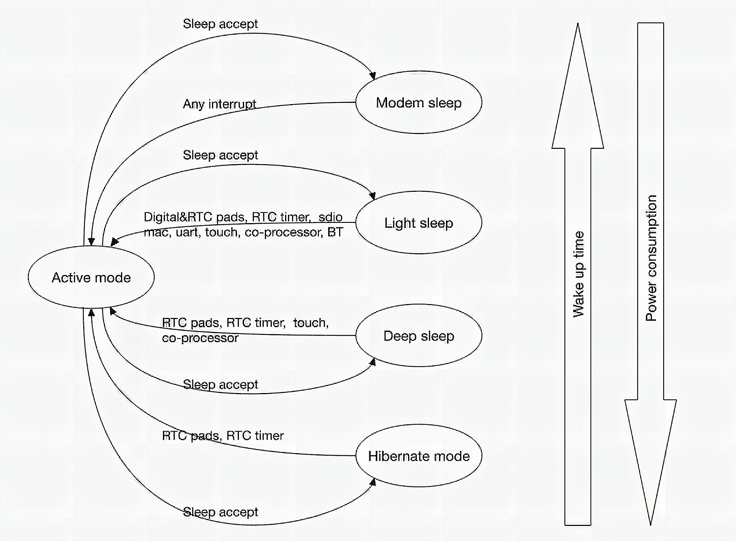
Going into an appropriate sleep mode is particularly important if you’re running off a battery. Doubly so if you’re using a WiFi enabled microcontroller. WiFi/BT subsystems use a lot of power.
| Mode | ESP8266 | ESP32 |
| Deep Sleep | 0.01mA | 0.01mA |
| Sleep | 0.9mA | 0.8mA |
| CPU | 15mA | 20mA |
| WiFi RX | 56mA | 100mA |
| WiFi TX | 320mA | 400mA |
These are power consumption figures gleaned from Espressif’s datasheets.
The increase in power consumption between the ESP32 running with the WiFi/BT block turned off (CPU only) and its deep sleep state is 2000x.
That’s the difference between running off a battery for over five straight years – and only having a single day of battery life.
This gap will only increase if you turn on the WiFi/BT block, as you would when transmitting or receiving data.
So if you’re planning to get any kind of meaningful battery life out of your device, you’ll have to learn how to get some (deep) sleep.
Components
Microcontroller
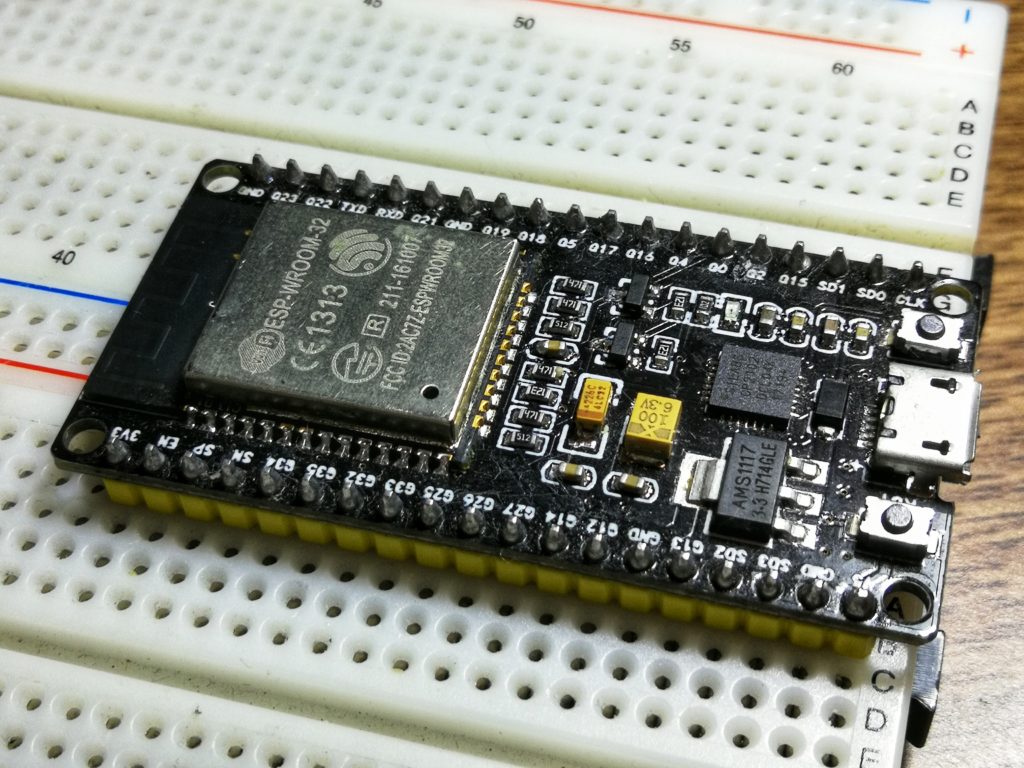
The ESP32 is a popular WiFi/BT enabled microcontroller with two Tensilisca Xtensa 32-bit LX6 cores running at 240MHz. The cores support dynamic frequency scaling, and you can configure the CPU to run at only 80MHz out of the box if you want to really save some power.
Software Setup
If you don’t have the ESP-IDF toolchain already installed, follow the instructions in this tutorial.
To configure the ESP32 core clock to run at 80MHz, run this command in your project directory to configure the ESP32 build.
make menuconfig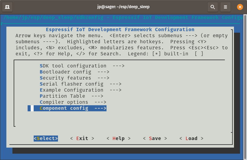
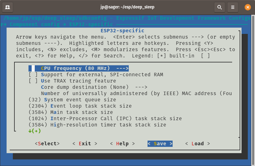
Go into the component config sub-menu. You should see a section which says “ESP32 specific”.
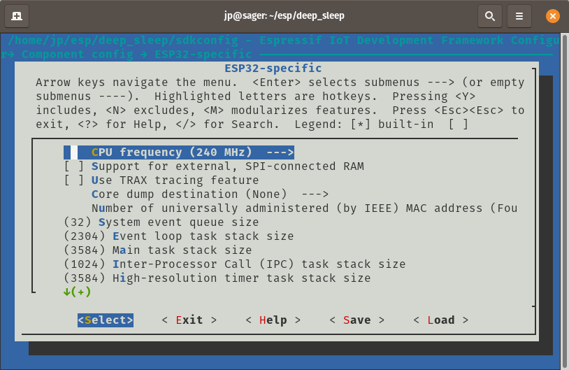
Now you can change the CPU frequency.
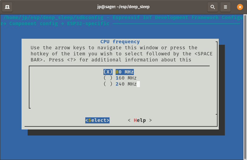
Setting it to 80MHz results in lower power consumption.
Now that you’ve set it to 80MHz, make sure to save your configuration settings.
Code
#include <stdio.h>
#include <string.h>
#include <stdlib.h>
#include <time.h>
#include <sys/time.h>
#include "freertos/FreeRTOS.h"
#include "freertos/task.h"
#include "esp_sleep.h"
#include "esp_log.h"
#include "esp32/ulp.h"
#include "driver/touch_pad.h"
#include "driver/adc.h"
#include "driver/rtc_io.h"
#include "soc/rtc_cntl_reg.h"
#include "soc/rtc.h" #define TOUCH_THRESH_NO_USE 0
static void calibrate_touch_pad(touch_pad_t pad); void app_main()
{ switch (esp_sleep_get_wakeup_cause()) { case ESP_SLEEP_WAKEUP_EXT1: { uint64_t wakeup_pin_mask = esp_sleep_get_ext1_wakeup_status(); if (wakeup_pin_mask!= 0) { int pin = __builtin_ffsll(wakeup_pin_mask) - 1; printf("Wake up from GPIO %dn", pin); } else { printf("Wake up from GPIOn"); } break; } case ESP_SLEEP_WAKEUP_TOUCHPAD: { printf("Wake up from touch on pad %dn", esp_sleep_get_touchpad_wakeup_status()); break; } case ESP_SLEEP_WAKEUP_UNDEFINED: default: printf("Not a deep sleep resetn"); } vTaskDelay(1000 / portTICK_PERIOD_MS); const int ext_wakeup_pin_1 = 25; const uint64_t ext_wakeup_pin_1_mask = 1ULL << ext_wakeup_pin_1; const int ext_wakeup_pin_2 = 26; const uint64_t ext_wakeup_pin_2_mask = 1ULL << ext_wakeup_pin_2; printf("Enabling EXT1 wakeup on pins GPIO%d, GPIO%dn", ext_wakeup_pin_1, ext_wakeup_pin_2); esp_sleep_enable_ext1_wakeup(ext_wakeup_pin_1_mask | ext_wakeup_pin_2_mask, ESP_EXT1_WAKEUP_ANY_HIGH); // Initialize touch pad peripheral. // The default fsm mode is software trigger mode. touch_pad_init(); // If use touch pad wake up, should set touch sensor FSM mode at 'TOUCH_FSM_MODE_TIMER'. touch_pad_set_fsm_mode(TOUCH_FSM_MODE_TIMER); // Set reference voltage for charging/discharging // In this case, the high reference valtage will be 2.4V - 1V = 1.4V // The low reference voltage will be 0.5 // The larger the range, the larger the pulse count value. touch_pad_set_voltage(TOUCH_HVOLT_2V4, TOUCH_LVOLT_0V5, TOUCH_HVOLT_ATTEN_1V); //init RTC IO and mode for touch pad. touch_pad_config(TOUCH_PAD_NUM8, TOUCH_THRESH_NO_USE); touch_pad_config(TOUCH_PAD_NUM9, TOUCH_THRESH_NO_USE); calibrate_touch_pad(TOUCH_PAD_NUM8); calibrate_touch_pad(TOUCH_PAD_NUM9); printf("Enabling touch pad wakeupn"); esp_sleep_enable_touchpad_wakeup(); // Isolate GPIO12 pin from external circuits. This is needed for modules // which have an external pull-up resistor on GPIO12 (such as ESP32-WROVER) // to minimize current consumption. rtc_gpio_isolate(GPIO_NUM_12); printf("Entering deep sleepn"); esp_deep_sleep_start();
} static void calibrate_touch_pad(touch_pad_t pad)
{ int avg = 0; const size_t calibration_count = 128; for (int i = 0; i < calibration_count; ++i) { uint16_t val; touch_pad_read(pad, &val); avg += val; } avg /= calibration_count; const int min_reading = 300; if (avg < min_reading) { printf("Touch pad #%d average reading is too low: %d (expecting at least %d). " "Not using for deep sleep wakeup.n", pad, avg, min_reading); touch_pad_config(pad, 0); } else { int threshold = avg - 100; printf("Touch pad #%d average: %d, wakeup threshold set to %d.n", pad, avg, threshold); touch_pad_config(pad, threshold); }
}
We’re going to make use of the ESP32’s built in capacitive touch sensor to wake up from deep sleep.
GPIO25 and GPIO26 will serve as capacitive touch enabled pins that will wake up the ESP32 if you touch them.
It’s a really cool feature to see in action.
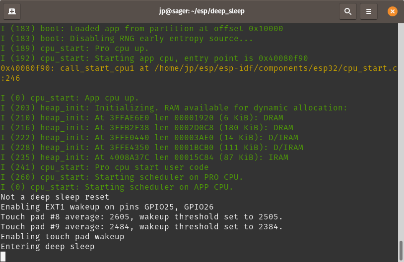
This should be the output of the serial monitor. “Not a deep sleep reset” indicates that it has yet to go into deep sleep. It should configure the touch pins and then immediately go to sleep.
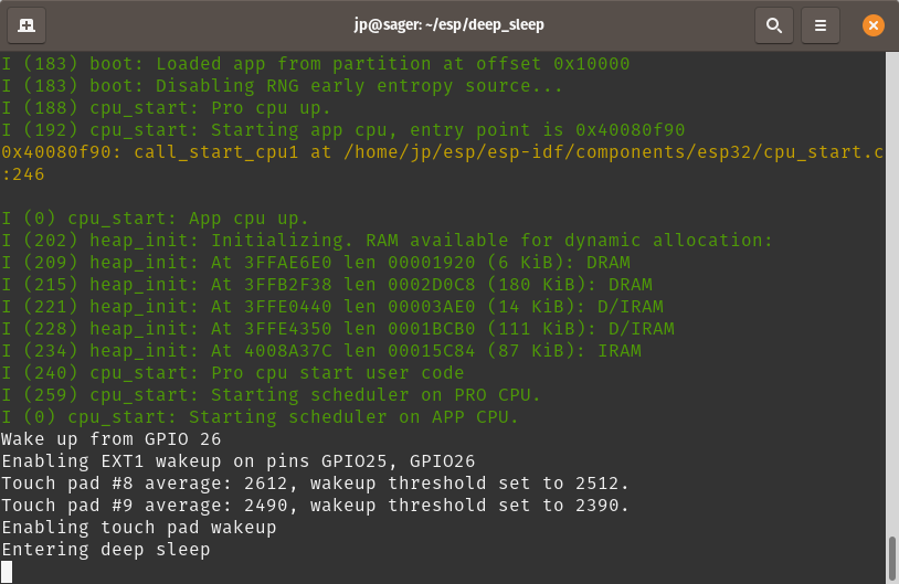
Touching either GPIO 25 or GPIO 26 should result in the ESP32 waking up momentarily, before going into deep sleep once again.

If you have an oscilloscope, you should be able to see the magnitude of difference in current consumption. Just use a low value resistor as a current shunt, then measure the voltage drop so you can see the current flowing into the ESP32.
Turning off logging or the serial debug feature of the ESP32 will also save a bit of additional power, but we’ll leave it on since this is how we’re getting output.
Using a dev board means there is some variability in power consumption figures. Some development boards will use a 3.3V regulator with truly atrocious quiescent current draw. This will heavily impact deep sleep figures. The ever popular AMS1117 used by most boards for example, will tend to draw several mA even without load. It is generally not suitable for a battery powered installation.
Some USB to Serial chips also don’t go into suspend mode or power off correctly when supplying power through the 5V pin.
These are just some of the possible culprits for seeing excessive current draw even in deep sleep mode.
That’s all folks!
Congratulations! You’ve finally learned how to sleep (on a microcontroller).
Your battery operated projects should now last much longer.
Good luck, and stay creative!
Frequently Asked Questions
What does this FreeRTOS: ESP32 Deep Sleep tutorial cover?
Overview Ever wonder how it’s possible for smart watches to run for several weeks on a single charge? Some are bound to run out of juice in just a couple of days.
Why does my ESP32 reset randomly during the FreeRTOS: ESP32 Deep Sleep sketch?
Usually brownout from a weak USB supply. Use a 5V/2A wall adapter or add a 470uF cap across VIN/GND. Second cause: WDT timeout — sprinkle yield() or vTaskDelay() in long loops.
Can I run ESP8266 code on an ESP32?
Mostly yes. ESP32 is API-compatible with most ESP8266 Arduino libraries plus dual core, BLE, and more I/O. Watch for analogRead range (ESP32 is 0-4095, 12-bit) and pin numbering.