
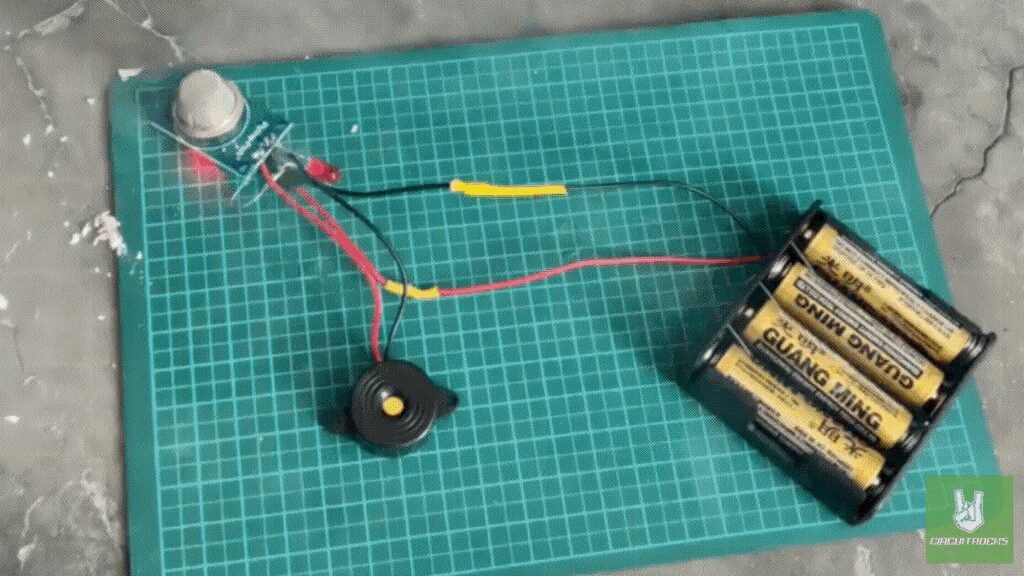
The Smoke Detector Circuit uses an MQ2 gas sensor to detect smoke and gases like propane, methane, and butane. It is reliable for spotting fire hazards early. When smoke is detected, the circuit sounds an alarm with a Piezo Buzzer. This loud sound quickly alerts people to act and stay safe.
The circuit runs on four AA batteries in a battery holder, making it portable and easy to use. An LED indicator lights up along with the sound alarm to give both visual and sound warnings. Resistors and jumper wires help control the current so the circuit works safely and efficiently.
Building this circuit teaches you how gas detection systems work and why they’re important for safety. It also helps you practice basic electronics skills like wiring and soldering. Using heat shrink and good soldering methods makes your connections stronger and longer-lasting. This project shows how different parts work together to create a reliable alarm system.
By making this project, you will improve your skills in soldering, wiring, and troubleshooting. You will also learn how to manage battery power. Overall, this practical electronics project gives you hands-on experience with detection and safety features, making it a great learning activity for anyone interested in electronics.
Components
Connection:
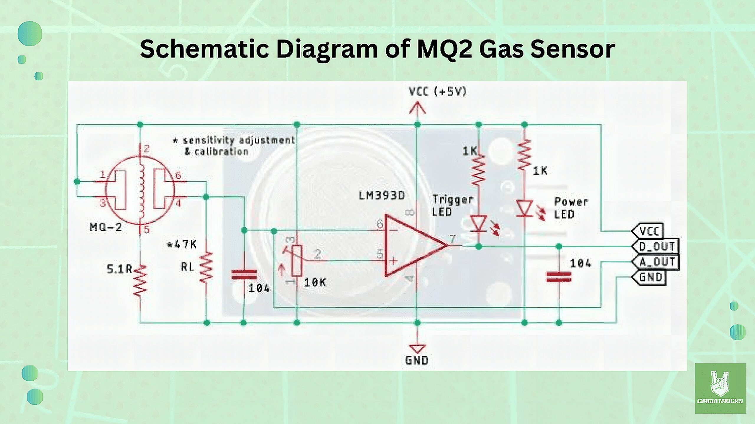
The schematic diagram of the MQ2 gas sensor module shows how it detects changes in gas concentration and turns these into usable signals. The MQ2 sensor works by changing its internal resistance when exposed to gases like smoke, propane, or methane. This change in resistance changes the output voltage, which is part of a voltage divider with resistors. As the gas levels change, so does the voltage at the output.
This voltage is sent to the LM393D comparator, which plays a key role in the detection process. The comparator compares the sensor’s output with a preset threshold (set by the potentiometer). If the gas concentration is higher than this threshold, the comparator’s output goes HIGH. This activates the digital output (D_OUT) pin and lights up the Trigger LED, signaling that dangerous gas levels have been detected.
The module also has an analog output (A_OUT) that shows the real-time gas concentration. This is useful if you want to measure the exact gas levels instead of just knowing if they crossed a certain limit. The LED indicators in the circuit help by showing when the power is on and when gas is detected. These features make the MQ2 module a useful tool for gas detection, providing both sound and light alerts to improve safety.
QUICK LINK
Frequently Asked Questions
What does this Smoke Detector CIRCUIT tutorial cover?
The Smoke Detector Circuit uses an MQ2 gas sensor to detect smoke and gases like propane, methane, and butane.
What's the working voltage of the Smoke Detector CIRCUIT?
Check the Sample Code section for the exact pinout — most maker-grade sensors run on 3.3V or 5V. Wire VCC to the matching rail, GND common with your MCU, data to a digital or analog pin.
Why does the Smoke Detector CIRCUIT read garbage or saturated values?
Three usual causes: wrong voltage rail, missing pull-up resistor on I2C lines (4.7k–10k to VCC), or a floating data pin. Double-check wiring against the diagram, then probe with a multimeter.