
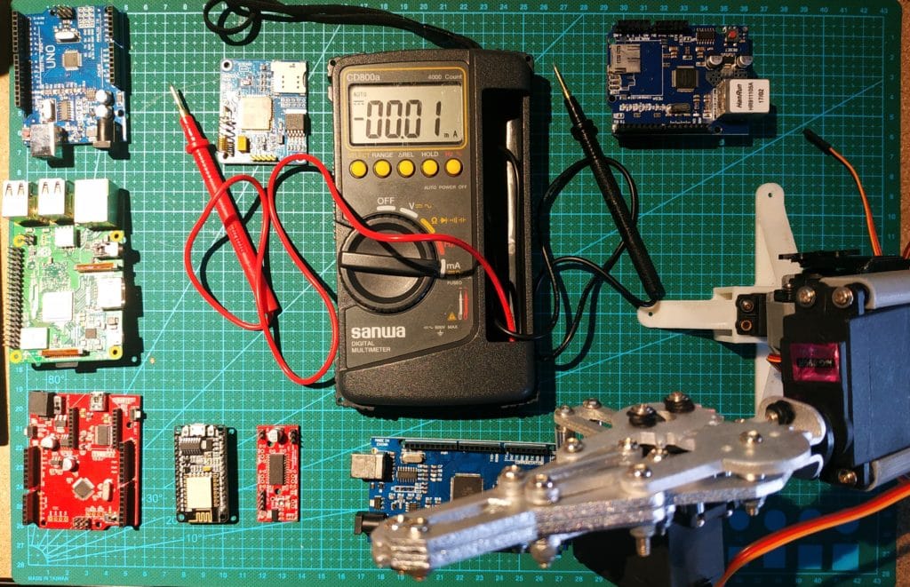
Circuit design always starts with a question of how to make things work. Engineers grab the nearest development boards, more often than not an Arduino, and rush to produce a working prototype. What comes next is the part that I’d like to share today. Optimization, specifically maximizing battery life.
To paint you a picture, the Arduino UNO consumes 42mA idle without a working code. That depletes an 18650 LiPo battery in less than 4 days! Add voltage regulators, some sensors, an ADC, a wireless communication module, and maybe indicator LEDs and that figure will easily rise. So much for four days, with this setup an individual cell won’t hold for even a day.
What will it take to make your battery last for a week? a month? or perhaps, a year? In this post, I’ll provide tips in choosing the right battery, and optimizing it to the point of unbeknownst heights.. Alright, maybe just 20 times better.
All About Batteries
Choosing the Right Battery
Batteries come in different flavors and there is traction in battery technology research. Every year, a lot of proposals and tech journal entries are made. There was a green Lithium-Sulfur battery, a Lithium-Ion ender battery IBM is preparing, and even a CO2 powered battery from MIT. All of these are exciting but not one of them are currently commercially available. I’ll update this when they come out but for now let’s take a look at what’s available.
Nickel-Metal Hydride
Nickel-Metal Hydride aka (NiMH) is a rechargeable battery technology. It’s cheaper but has low density. This means it discharges easily. It is commonly used in devices where input voltage doesn’t really matter. Electric shavers for example use NiMH. You’ll notice them running more slowly as the battery discharges. Input voltage drops but it still continues to work. Each cell outputs 1.2V.
Alkaline
Alkaline is probably the most common battery technology. They are the ones hanged nearest at the counter on your local hardware store. They come in AA and AAA packaging. These cells does not last longer than LiPo but they’re cheap and safe to use. They won’t break when connected in reverse, instead they heat up just a little. They’re perfect for beginners. Alkaline cells usually output 1.2 or 9V.
Lithium-Ion Polymer
Lithium-Ion Polymer aka LiPo is the battery technology currently with highest density. They are also rechargeable. Laptops and cellphones predominantly use this battery. They require special charging since they tend to explode when charged with current outside of their limits. Mishandling LiPo often ends up in flames. Samsung experienced this firsthand with their Note 7. A LiPo cell outputs 3.7V.
Coin Cells
Coin cells are the kings of low power devices. They are cheap and they have a lot of variations using previously mentioned chemistry and technologies. They come in different sizes. Outputs available are 1.5V and 3V. These coin cells are perfect for testing LEDs and powering up small embedded projects.
Placing Batteries in Series and Parallel
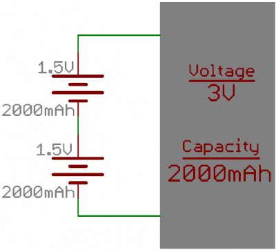
You may be thinking, how can a single cell of 1.5V power a circuit that needs a higher rating, 3V for example, to function? Well, you can produce higher voltages by placing the cells in series. Doing this adds the voltages together. This concept can be easily explained by an image I saw from SparkFun.
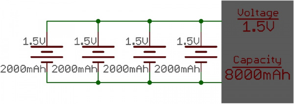
On the other hand, placing the cells in parallel gives you a larger capacity.
Computing capacity
Battery capacity is measured in Ampere Hour or Ah but we normally use Milliampere hour or mAh in portable electronics. To show you how much battery capacity you’ll need, let’s have this circuit from a previous project as an example.
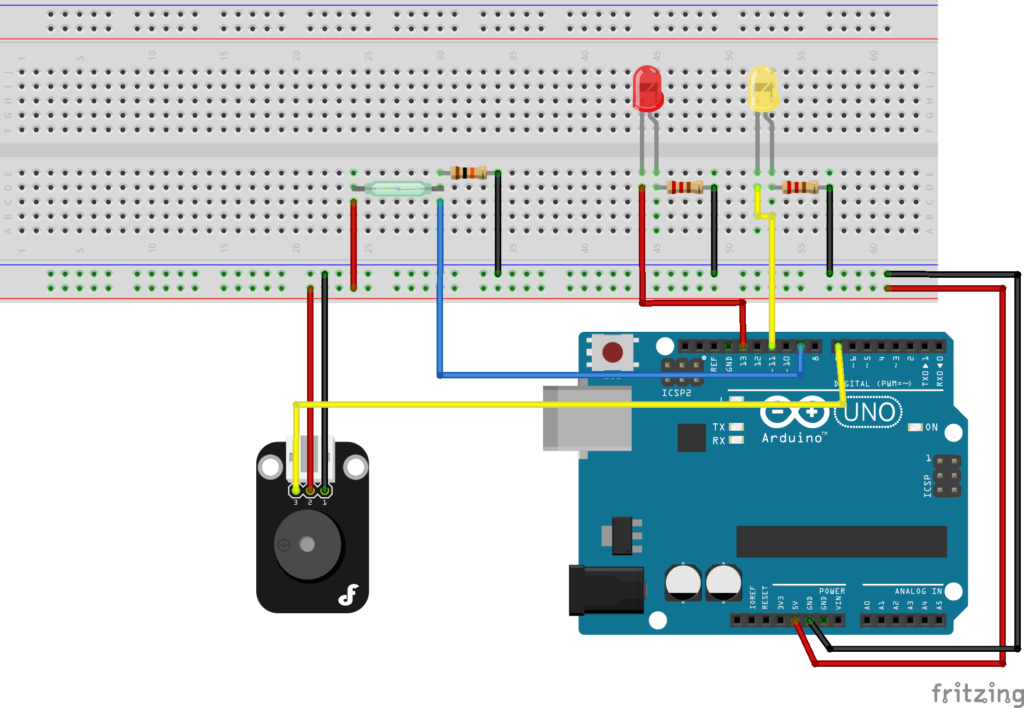
A pretty simple circuit, isn’t it? I used an Arduino UNO, a Magnetic reed switch, a Digital Speaker Module, 2 LEDs, 2 220? resistors, and a 10k? resistor to detect if a door is open and play a pre-programmed tune. Let’s have all the components in a table to understand them better.
| Component | Current Rating |
| Arduino UNO | 42mA |
| Magnetic reed switch | 0mA |
| Digital Speaker Module | 250mA |
| 5mm Red LED | 10mA |
| 5mm Yellow LED | 10mA |
For these hypothetical ratings, the current draw would be:
42mA + 250mA +2(10mA) = 312mA
For this project, I can use any type of battery technology since it’s not that particular with precision. The most optimal choice would be a AA cell since it’s affordable but I already had an 18650 LiPo so I used that. 18650 LiPos outputs 3.7V and have 2000-3500 mAh capacity. I used a step up converter to raise the voltage to 5V for the Arduino. Another option would be adding another 18650 in series to have an output of 7.4V and using a step down converter to have a 5V output.
To calculate how long the cells would last for this circuit, I used this equation:
Battery Capacity (mAh) / Current Draw (mA) = Battery Life (h)
For my circuit that would be:
3500 mAh / 312mA = 11.217 hours
That means with both LED working and the speaker playing continuously, the battery would ideally last up to 11.217 hours. To get a realistic estimate, we may assume only 75% of the battery life. That’s 8.413 hours.
So…
As you can see, we only have two options in improving battery life. One is adding a cell in parallel to increase capacity. The other one is reducing the device current draw. The first method is simple, convenient, and fail-safe but bad if you’re downsizing your project. For an overall improvement, we need to come up with a way of increasing amount of work with the same amount of charge. Let’s discuss this further in the next section.
Power Saving Methods
Improving battery life by implementing power saving techniques is popular in the electronics industry. Sometimes, there are even whole departments assigned for just optimizing device power consumption.
Engineers have developed plenty enough techniques for us to use. Sometimes, it’s about hardware. Other times, software. I’ll discuss all of these below.
1. Using Lower Voltage
“What’s the minimum voltage do each my components need?”. I ask myself that every project I make. Sensors usually give better performance with higher voltages but do you actually need the added juice? If 3.3V gets the job done then ditch the 5V input and lessen your current draw by a significant amount. A bit of a caveat in using a lower 3.3 volts with some micro controllers (in this case an Atmega328P) is that, according to its datasheet, the maximum frequency is only 13MHz. You should reduce the clock speed if you don’t want to have issues in timing, or etc.
2. Reducing Clock Speed
Reducing clock speed doesn’t only lessen the stress on your microcontroller, it also adds battery life. Reduce them if your project doesn’t require you to process large sets of instructions.
An Arduino working at 8MHz instead of 16MHz saves up to 5 mA of current draw. You may think that’s not much but that trick actually adds hours of operation for your device.
3. Removing Unnecessary Hardware
This might be obvious but if you don’t need the peripherals better ditch it. This can help in downsizing as well as power saving. A good example of this is the Arduino. Arduinos are called development boards for a reason. They are excellent for prototypes. They’re convenient because they already have voltage regulators, SC and OC protection, a USB bridge, an indicator LED, and etc. in one package. For fine tuned products though, it’s better to use an individual micro controller and work your way up there.
Removing unnecessary hardware drastically lowers current draw but working with bare micro controllers are more complex and requires more time to do.
4. Turning off Unnecessary Internal Modules
Now that we’re down to the Atmega328P, let’s further improve our battery life by disabling unneeded internal modules. We’ll dive right into the Power Reduction Register (PRR).
The PRR lets you disable features inside the microcontroller by altering various bits. The internal modules and their corresponding bits are as follows:
- Bit 7 – PRTWI: Power Reduction TWI
- Bit 6 – PRTIM2: Power Reduction Timer/Counter2
- Bit 5 – PRTIM0: Power Reduction Timer/Counter0
- Bit 3 – PRTIM1: Power Reduction Timer/Counter1
- Bit 2 – PRSPI: Power Reduction Serial Peripheral Interface
- Bit 1 – PRUSART0: Power Reduction USART0
- Bit 0 – PRADC: Power Reduction ADC
You can disable everything in one go with the macros power_all_disable() and power_all_enable().
#include <avr/power.h> void setup () { power_all_disable(); // turn off all modules
} // end of setup void loop () { }
If you want to enable or disable selected modules only,
Enable
- power_adc_enable(); // ADC converter
- power_spi_enable(); // SPI
- power_usart0_enable(); // Serial (USART)
- power_timer0_enable(); // Timer 0
- power_timer1_enable(); // Timer 1
- power_timer2_enable(); // Timer 2
- power_twi_enable(); // TWI (I2C)
Disable
- power_adc_disable(); // ADC converter
- power_spi_disable(); // SPI
- power_usart0_disable();// Serial (USART)
- power_timer0_disable();// Timer 0
- power_timer1_disable();// Timer 1
- power_timer2_disable();// Timer 2
- power_twi_disable(); // TWI (I2C)
With no need of modifying your circuit, disabling these modules can save you up a few milliamps. Make no mistake these software tricks can be done with other microcontrollers as well. They may have different macro but just like everything that’s only one google search away from finding out.
5. Turning Off Brown-Out Detection
Brown-out detection makes sure your IC doesn’t drop below a certain system voltage rating. It automatically powers down until desired voltage is met. You can save some current draw disabling this but it also introduces possible flash memory corruption.
To disable brown-out detection in an Atmega328P, use this code:
#include <avr/sleep.h> void setup () { // turn off brown-out enable in software MCUCR = bit (BODS) | bit (BODSE); // turn on brown-out enable select MCUCR = bit (BODS); // this must be done within 4 clock cycles of above interrupts (); // guarantees next instruction executed sleep_cpu (); // sleep within 3 clock cycles of above
} // end of setup void loop () { }
You can also disable it by removing the extended fuse (efuse) in AVRdude:
avrdude -c usbtiny -p m328p -U efuse:w:0x07:m6. Turning Off ADC
Another way to save battery life is by disabling the built-in analog to digital converter of the Atmega328P. Analog to Digital converters are of paramount importance in remote monitoring analog data from sensors. This is what converts your analog signal (temperature, sound, light, and etc.) to digital data your micro controller can read. Make sure you implement this line of code cleverly. I haven’t used this yet but if it were me I’d make the device read the data, store it in a variable, disable the adc, and do the processes needed to transmit it.
// disable ADC ADCSRA = 0; Disabling the ADC can potentially move one decimal point in the amount of your current draw.
7. Sleep
Sleep mode is perhaps the most popular term in all power management techniques. All the latest components seem to have them. You can easily enable sleep mode in an Arduino with a few lines of code.
#include <avr/sleep.h> void setup () { set_sleep_mode (SLEEP_MODE_PWR_DOWN); sleep_enable(); sleep_cpu (); } // end of setup void loop () { }
As previously mentioned, an idle Arduino with no code approximately draws 42mA of current. This goes down to 34mA in sleep mode.
Using the bare Atmega328P, we can set it down to lower ratings using different sleep modes. The Atmega328P normally runs at 20mA. By substituting these different modes, we can have:
set_sleep_mode (SLEEP_MODE_PWR_DOWN); Sleep modes and power consumption:
- SLEEP_MODE_IDLE: 15 mA
- SLEEP_MODE_ADC: 6.5 mA
- SLEEP_MODE_PWR_SAVE: 1.62 mA
- SLEEP_MODE_EXT_STANDBY: 1.62 mA
- SLEEP_MODE_STANDBY: 0.84 mA
- SLEEP_MODE_PWR_DOWN: 0.36 mA
Idle mode keeps the main clock running so it basically wakes up every millisecond. ADC keeps the ADC. Power Save keeps an external clock running. Standby mode keeps the oscillator running so that it can wake up faster.
8. Turning Off Watchdog Timer
Watchdog timers (WDT) are electronic timers that automatically reset your devices when a problem occurs. Basically, it counts down from a set value to zero. When it reaches zero, it times out and resets your device. In normal operation, the microcontroller periodically resets the WDT to prevent it from timing out. To disable it, you can use:
// watchdog interrupt
ISR (WDT_vect) { wdt_disable(); // disable watchdog
} // end of WDT_vect
9. Using Better Voltage Regulators
If you’re gonna use bare bones Atmega328P, you’ll probably use a voltage regulator to maintain a constant input voltage for your micro controller. As I mentioned on an analysis of the Arduino schematic, the Arduino UNO uses a 5V linear voltage regulator NCP1117ST50T3G. Linear regulators are wonderful but they do heat up a lot, and in electronics, heat means wasted energy. This heat is caused by the difference between the input and output voltages in the voltage regulator while on the other hand, current remains the same. You can measure the wasted energy with the equation below.
P = (Vin – Vout) * I
You can increase battery life with a low dropout (LDO) switching regulator. Switching regulators provides an option of having different input and output currents. Dropout voltage is an amount of voltage difference between the output voltage and the input voltage. When dropout voltage is met, the regulator stops voltage regulation and lets the whole amount of voltage punch through your circuit. Linear regulators normally drops out at 2V while LDOs drops out at 100 to 200mV. Less current and less voltage difference means less heat dissipated while less heat means less power wasted.
10. Using a Separate Power-Controller Circuit
Finally, for the magician’s last trick. The coup de grace of saving battery life is by using a separate power controller module. I’ve just recently read about this but basically it functions like this. Suppose you can’t discard the Arduino UNO. You may be using one of its shields and compatible modules. Adding a separate circuit to wake your board up for a second and letting it return to sleep drastically lowers your current draw while still enjoying all of the UNO’s eccentricities. I’m planning to make one in the coming days so better stay tuned!
Postscript
Hey turns out there’s one more power saving trick you can use. It’s an interesting sleep mode called deep sleep. JP wrote about it here. Better check it out!
References
https://learn.sparkfun.com/tutorials/reducing-arduino-power-consumption
https://www.alanbmitchell.wordpress.com/2011/10/02/operate-arduino-for-year-from-batteries/
https://www.analog.com/en/analog-dialogue/articles/low-dropout-regulators.html
https://www.gammon.com.au/power
Frequently Asked Questions
[faq] [faq_q]What is the single biggest battery saver on ESP32 / ESP8266?[/faq_q] [faq_a]Deep sleep. An ESP32 in deep sleep draws around 10 microamps versus 80 mA active, an 8000x reduction. If your project does not need to be awake constantly, deep sleep alone often extends battery life from days to months.[/faq_a][faq_q]Should I use lithium-ion or alkaline for IoT projects?[/faq_q] [faq_a]Lithium-ion (18650 or LiPo) for projects with charging access and a higher capacity-to-weight ratio. Alkaline AA for set-it-and-forget-it sensors that need to last a year and have replaceable cells.[/faq_a][faq_q]Does Wi-Fi or Bluetooth use more power?[/faq_q] [faq_a]Wi-Fi uses far more, often 80-150 mA active. BLE drops to around 10 mA active and is built around quick advertising bursts. For battery projects, BLE or LoRa beats Wi-Fi by an order of magnitude.[/faq_a][faq_q]How do I measure my project actual current draw?[/faq_q] [faq_a]A USB power meter shows steady draw. An oscilloscope or specialized tool like the Nordic Power Profiler Kit captures bursty patterns from sleep/wake cycles, which a multimeter misses.[/faq_a][faq_q]What is a good battery-life target for a remote LoRa sensor?[/faq_q] [faq_a]One year on a 2500 mAh 18650 cell is achievable if the sensor wakes every 10-15 minutes, transmits briefly, then deep-sleeps. Faster reporting cuts that proportionally.[/faq_a][/faq]Frequently Asked Questions
What does this A Complete Guide to Increasing Your Device Battery Life tutorial cover?
Table Of Contents All About Batteries Choosing the Right Battery Nickel-Metal Hydride Alkaline Lithium-Ion Polymer Coin Cells Placing Batteries in Series and Parallel Computing capacity So… Power Saving Methods 1.
What's the working voltage of the A Complete Guide to Increasing Your Device Battery Life?
Check the Sample Code section for the exact pinout — most maker-grade sensors run on 3.3V or 5V. Wire VCC to the matching rail, GND common with your MCU, data to a digital or analog pin.
Why does the A Complete Guide to Increasing Your Device Battery Life read garbage or saturated values?
Three usual causes: wrong voltage rail, missing pull-up resistor on I2C lines (4.7k–10k to VCC), or a floating data pin. Double-check wiring against the diagram, then probe with a multimeter.