
We’ve already tackled the schematic diagram of the famed Arduino UNO. It is now time to assemble it in your own breadboard! Here are the steps and some simple explanation on how to make an Arduino on a breadboard.
Introduction
What I love about Arduino is that it is so unselfish of its technology. It’s not easy for engineers to just hand away their designs for anyone else to fiddle with. Normally, they would just patent the hell out of their designs. Make profit. Create a company out of the product. Fortunately though, it is not the case for Arduino. They don’t mind sharing their brainchild to everyone. Thus, making it as everyone’s child. Nurtured by millions of developers worldwide, it turned out as the monster baby of the development board world (in a good way of course).
The problem is, if you’re still new to electronics, even with the designs available, it would still be hard to follow. Also, there’s a high chance you will be confused on what components to buy. That’s what the article is for. I’ll provide step by step procedures on how to create the board. They will be easy to digest and follow. I included the problems I encountered building it so there’s some troubleshooting bonus sprinkled in.
For the DIY kit, you can just order them here. For the USB to TTL cable, here.
The Boarduino

The Boarduino kit from Adafruit is an Arduino clone designed to fit easily in a breadboard. They are pretty convenient especially in the first stages of development. You can program it easily using the Arduino IDE.
Here’s what it looks like assembled:

Image courtesy of Adafruit
However, we won’t jump to building the Boarduino just yet. We’ll make our Arduino piece by piece in the breadboard. This way we’ll understand how every component works.
There are two kit variants: DC and USB. The DC kit provides a DC power jack coupled with a 5V voltage regulator. The USB kit has an on-board USB chip. I got the DC one because I’ll use it later with a power adapter on a future project. Using a DC kit also means I need a USB to TTL cable to communicate with the microcontroller. Also, take note that the Atmega328PU that I got from our store is already programmed with the Arduino bootloader. In case your chip hasn’t been programmed yet, you may use an AVR ISP programmer. With that, you can burn the bootloader using this tool in the Arduino IDE:
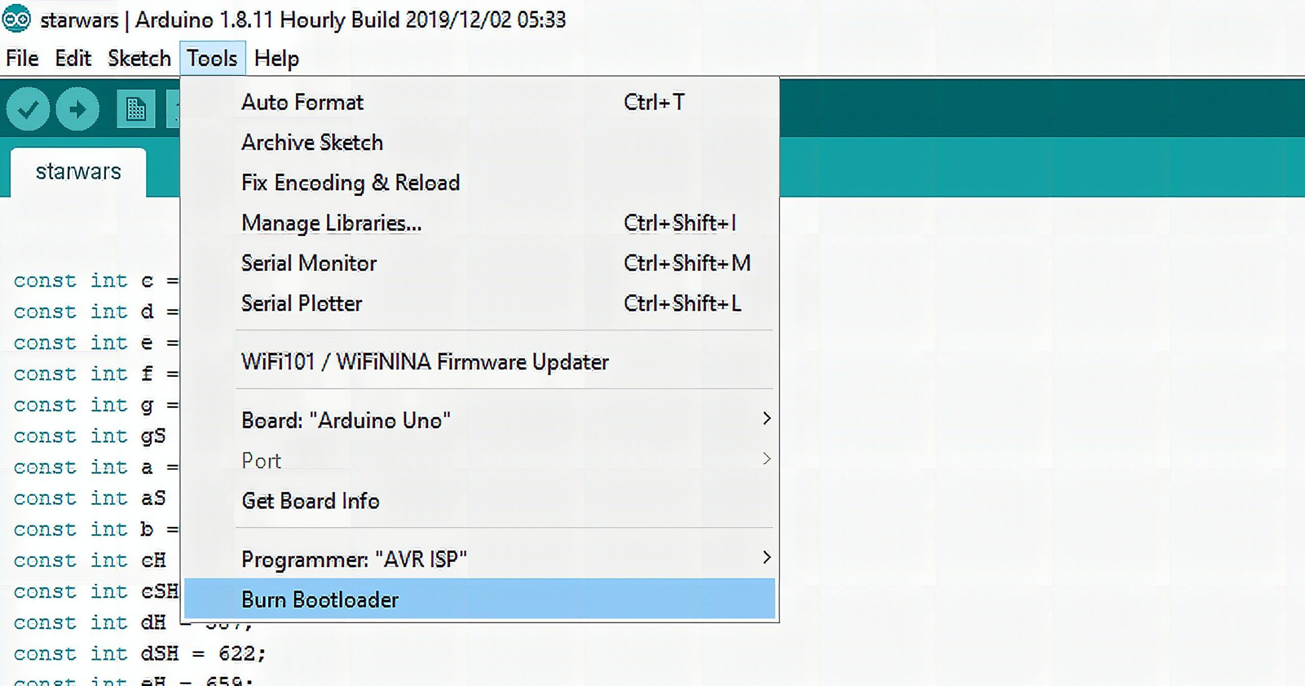
Don’t mind the opened file. The power of the dark side made me forgot to close it.
Burning the Arduino bootloader takes a few minutes. After that, you can already upload your programs to the micro controller.
Components
The DC boarduino components are:
| Name | Description | More Info | Qty |
| IC1 | Microcontroller (preprogrammed with Arduino bootloader when purchased in a kit). | ATmega328P-20PU | 1 |
| IC1′ | 28-pin socket | 28 pin socket | 1 |
| X1 | 16.00 MHz ceramic oscillator | 16 mhz ceramic resonator | 1 |
| 2.1mm Power Jack | CUI PJ-202AH | 1 | |
| D1 | 1N4001 diode | Generic 1N4001 | 1 |
| IC2 | 5V regulator7805 TO-220 package | 7805 | 1 |
| C1 C2 C5 C6 (opt) | Bypass capacitor0.1uF ceramic | Ceramic Capacitor | 3 or 4 |
| C3 | Electrolytic capacitor47uF / 25V (or higher) | Electrolytic Capacitor | 1 |
| C4 | 100uF/6.3V capacitor (or higher)(the image shows a 10V but 6.3V is fine) | Electrolytic Capacitor | 1 |
| R1 | 10K ohm 1/4W 5% resistor (brown black orange gold) | Generic Resistor | 1 |
| R2 R3 | 1.0K 1/4W 5% resistor (brown black red gold) | Generic Resistor | 2 |
| D3 | 3mm red LED | 3mm red diffused | 1 |
| D2 | 3mm green LED | 3mm green diffused | 1 |
| SW1 | 6mm tact switch button | 6mm tact switch | 1 |
| ICSP | 6 pin header, 0.1″x0.1″ spacing | 2×3 pin header | 1 |
| 40 pin male header, 0.1″ spacing | 0.1″ male header strip | 1 | |
| Jumper | 1 | ||
| PCB | Circuit board | Adafruit Industries | 1 |
Check if everything is there then we will proceed to the first step.
Power Supply
We’ll use the Boarduino schematic as a guide. Also, it is important to know that designs like this are not set in stone. We can add more components as well as remove some. It will all depend on what you’re going to use the circuit board for.
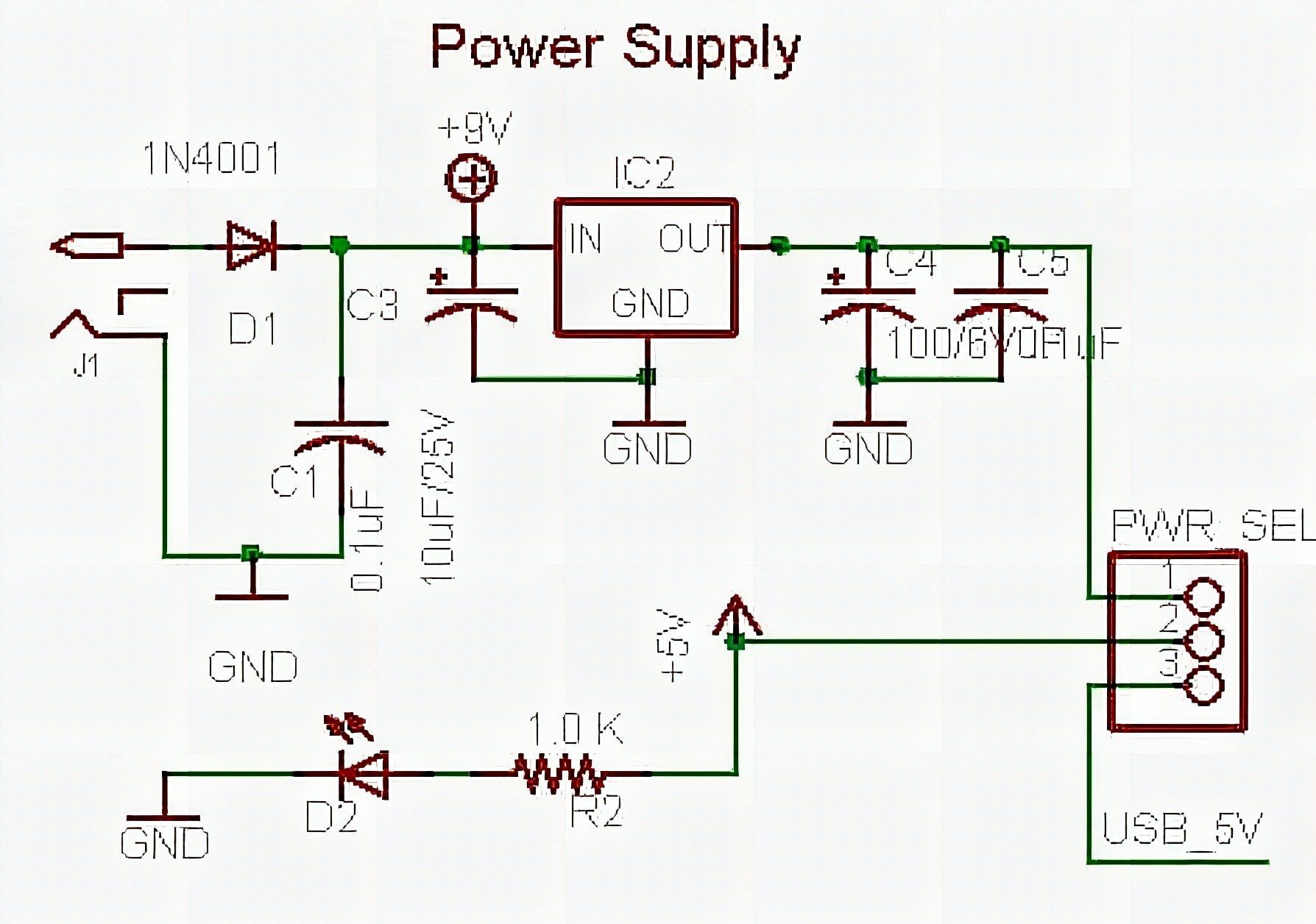
For those who read my previous post about the Arduino UNO’s schematic, this module should already look familiar. Powering up with a DC adapter means you’ll need a couple of components to protect your board from AC instabilities. First off is a reverse polarity protection diode D1. This makes sure that the current only flows in one direction. The ceramic capacitors C1 and C5 acts as bypass/decoupling capacitors. They isolate the noise to this power module so it won’t affect the microcontroller. On the other hand, the electrolytic capacitors C3 and C4 are filtering capacitors, further smoothing the electricity in and out of the voltage regulator IC2. D2 is an LED that lights up when you connect a DC power adapter.
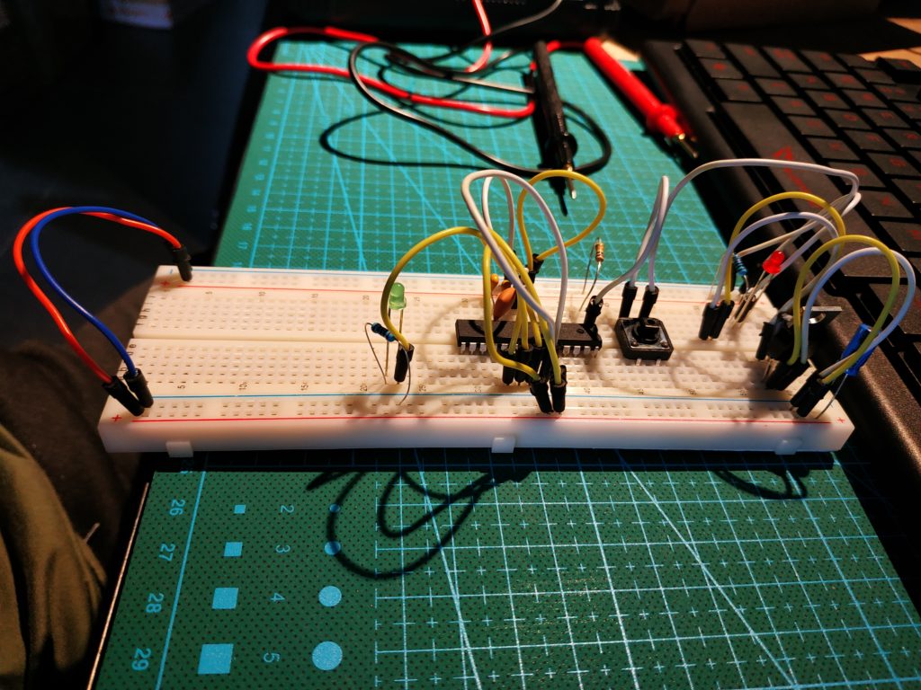
Only at this point that I realized the DC jack won’t fit in the breadboard. I had to improvise so I switched into using the USB as power supply instead. I studied the guide from the Arduino website and assembled the components like this:

With this setup, there’s still an option of connecting the DC power jack in the yellow and white wires (red and black wires are in short supply). I did not include the protection diode because I was going to use USB power anyway. I also ditched the ceramic capacitors to save space. Take note that this will increase the noise susceptibility of the board.
Microcontroller

The schematic from the Adafruit website has the Atmega168P as the microcontroller of the Boarduino. The kit I have has the Atmega328PU with it. The only major difference between these two is that the Atmega328PU has double the programming space.
In the schematic, you can see where to connect the pins from the micro controller to their respective functions. The tact switch button S1 connected to pin 1 is normally connected to the supply. If pressed, it will connect to the ground and will disconnect the circuit. This serves as the reset button of the microcontroller.
Pins 1, 2, and 3, along with the Vcc and GND should connect to a FTDI USB-TTL cable/module if you wish to program the microcontroller through your computer. I used this cable from our store.
FTDI Cable

The red, black, white, green, blue, and yellow wires are connected to the 5V, GND, Receiver, Transmitter, Clear to Send (CTS), and Ready to Send (RTS) respectively.
The external clock is connected to pins 9 and 10 of the micro controller. Finally, the remaining pins are for the GPIO headers.
Using the Boarduino kit, I did the circuit like this:

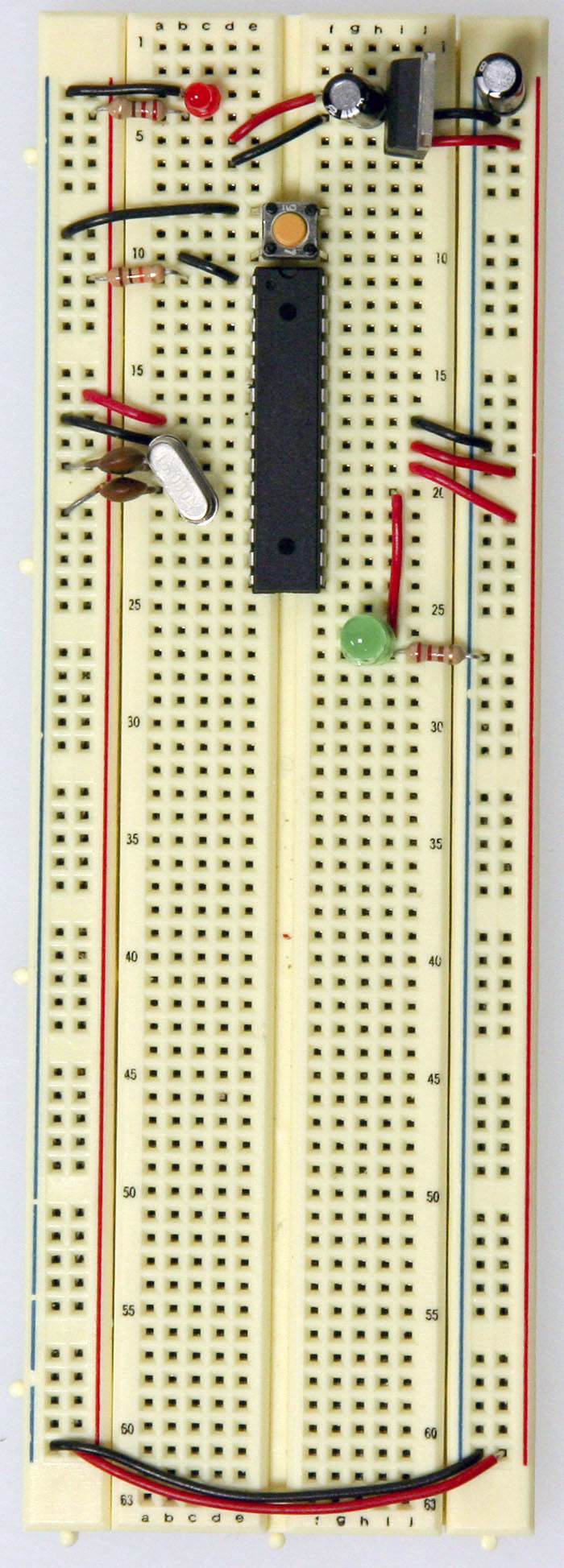
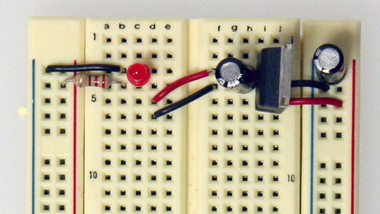
The clock used for the Boarduino is a 16 MHz ceramic resonator/oscillator (left) while in the Arduino website a 16 MHz crystal (right) is used. The main difference between these two is that the ceramic resonator has three pins while the crystal has two.
The ceramic resonator has three pins because it already has built-in stability capacitors inside. The two outer pins should be connected to the clock in and clock out of the micro controller, which in this case are pins 9 and 10 respectively. The middle pin should be connected to the ground. Either outer pin of the ceramic resonator can be used for clock in and clock out since this discrete component is symmetric.
If you’re using a crystal, you need to connect it with a pair of ceramic capacitors for both pins.
Testing the Board
By now, our breadboard Arduino is fully functional. You can further minimize the board by removing other features like the LED indicators and the reset switch. I connected the FTDI cable temporarily so that I can do simple tests.

USB power works well.

Arduino IDE recognizes the board.

Program has been uploaded successfully.
It’s a different kind of fulfillment building the Arduino from individual components. It’s going to feel like you’ve been enlightened. Everything in the board suddenly make sense. Loads of project ideas gush into your brain as the Atmega328P powers the blink circuit you’ve setup to test.
Yeah maybe I’m overselling it a little.
However, it’s still good to know. Who knows? You may design your own development board in the near future.
If you like this post, check out my previous work with the NRF24L01+. See you next time!
References
Frequently Asked Questions
What does this Making Your Own Arduino Using the Atmega328PU tutorial cover?
We’ve already tackled the schematic diagram of the famed Arduino UNO.
Can I use an Arduino Nano or Mega instead of UNO for the Making Your Own Arduino Using the Atmega328PU build?
Yes. Nano shares the same ATmega328P and pinout. Mega has more I/O if you outgrow UNO. The code stays the same — just match the pin numbers used in the Sample Code section.
Why does my Making Your Own Arduino Using the Atmega328PU sketch fail to upload?
Usually wrong COM port, missing CH340/CH341 driver for clone boards, or another program holding the serial port. Disconnect the board, install the driver, reselect the port, retry.