

I still can’t believe how much this board costs considering its features. If you’re tired of messy wires and would like to put on some sophistication on your DIY Arduino projects, stay tuned because today we’ll be doing wireless communications using the NRF24L01+ RF Transceiver Module.
Overview
The NRF24L01 RF GFSK Transceiver is just the size of a thumb, but it already packs a frequency synthesizer, power amplifier, a crystal oscillator, a modulator/demodulator, and a Enhanced ShockBurst™ protocol engine. It operates at the globally recognized ISM band (more on that later). Moreover, it can cover up to 100m and has power saving modes which is especially neat for remote monitoring sensor data. All that for less than a hundred pesos.
Product Specifications
The NRF24L01+ runs at the worldwide 2.4 – 2.5 GHz ISM band using GFSK modulation. It has 250 kbps – 2Mbps baud rates, and with a lower baud rate, it can reach up to 100m.
2.4 – 2.5 GHz is one of the ISM (Industrial, Scientific, and Medical) bands for wireless communications. These are radio bands that are reserved for the use of unlicensed low-powered devices, usually cordless phones, Bluetooth devices, near field communication (NFC) devices, and wireless computer networks (WiFi) devices. The Philippines has 12 ISM bands and since 2.4 – 2.5 GHz is a globally recognized ISM band, we can use the device here worry-free.
The device operates at 2,400 – 2,525 MHz with 1 MHz spacing particularly, which means it has 125 different channels ready for wireless communications. As I did, you’ll have to specify the channel you’re going to use in your software (more on this later). Also, the NRF24L01+ can actively listen to up to 6 devices so creating a wireless network with them is possible.
Finally, since we can’t transmit digital signals on air, it has to be modulated first. The NRF24L01+ uses Gaussian Frequency-Shift Keying modulation scheme.
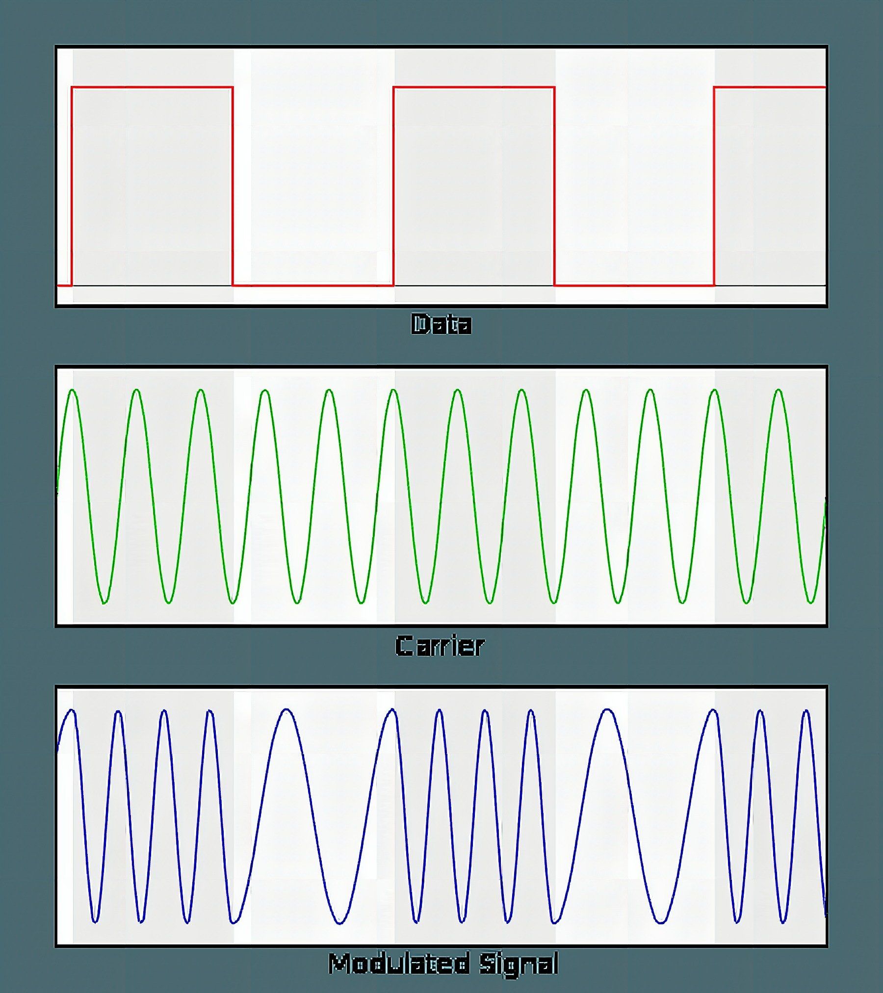
Image courtesy of Wikipedia
Frequency-shift keying is a modulation scheme in which data is transmitted through frequency changes of a carrier signal. GFSK is just like this but with the transitions of every frequency change smoothed by a Gaussian filter. This reduces inter-channel interference and spectral width, improving signal integrity.
Quick Reference Data from Product Datasheet
| Parameter | Value | Unit |
| Minimum Supply Voltage | 1.9 | V |
| Maximum Output Power | 0 | dBm |
| Maximum Data Rate | 2000 | kbps |
| Supply Current in TX mode @ 0dBm | 11.3 | mA |
| Supply Current in RX mode @ 2000 kbps | 12.3 | mA |
| Temperature Range | -40 to +85 | °C |
| Sensitivity @ 1000 kbps | -85 | dBm |
| Supply current in Power Down mode | 900 | nA |
It only needs 1.9 V to operate (less than the Arduino 3.3V standard). It is also 5V tolerant, which means you won’t need a logic level converter when connecting to a 5V-normal logic microcontroller.
A power level of 0 dBm corresponds to a transmitting power of 1 milliwatt. The board’s output power can be programmed to 0dBm, -6 dBm, -12 dBm and -18 dBm. At 0 dBm, the board consumes 11.3mA (even less than a single LED). To top it all off, at standby mode it runs at around 26µA, and at power down mode, it consumes a merely 900nA, enabling months to years of battery life with an 18650 battery or a coin cell.
SPI Interface
The board uses SPI protocol to communicate with the microcontroller. In my case, I used the Arduino UNO (Note that every board may have their SPI pins in different locations). SPI supports faster full-duplex communication but is more susceptible to noise than I2C. SPI only supports one master device, while I2C supports multiple. This is why in the NRF24 Network library, the network topology used is Tree.
Pinout
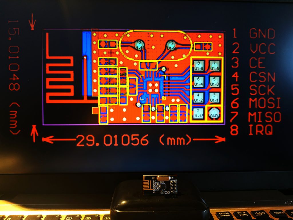
| 1 | GND | This is the ground pin. It is enclosed in a white square. |
| 2 | VCC | This is where you’ll connect the supply pin. This can be between 1.9 to 3.6 V. |
| 3 | CE | This is an active HIGH pin. This controls whether the NRF24L01+ transmits or receives. |
| 4 | CSN | This is an active LOW pin. This pin is normally HIGH but when turned LOW, it listens to the SPI port. |
| 5 | SCK | Accepts clock pulses provided by the SPI bus master. |
| 6 | MOSI | SPI Input. |
| 7 | MISO | SPI Output. |
| 8 | IRQ | Alerts the master when new data is to be sent. |
On Programming
On the software side, I used a ready made library. You can download it here:
Codes
Transmitter Side:
//Include Libraries
#include <Arduino.h>
#include <SPI.h>
#include <nRF24L01.h>
#include <RF24.h> //create an RF24 object
RF24 radio(7, 8); // CE, CSN //create a byte array for the address
const byte address[6] = "00001"; void setup() { //initalize nrf24 radio.begin(); //set the address radio.openWritingPipe(address); //set power amplifier level radio.setPALevel(RF24_PA_MIN); //set module as transmitter radio.stopListening();
} void loop() { const char text[] = "Hello, World"; radio.write(&text, sizeof(text)); delay(1000);
}
Receiver Side:
//Include Libraries
#include <Arduino.h>
#include <SPI.h>
#include <nRF24L01.h>
#include <RF24.h> ////create an RF24 object
RF24 radio(7, 8); // CE, CSN //create a byte array for the address
const byte address[6] = "00001"; void setup() { Serial.begin(9600); //initalize radio.begin(); //set address radio.openReadingPipe(0, address); //set power amplifier level radio.setPALevel(RF24_PA_MIN); //set module as receiver radio.startListening();
}
void loop() {
//this loop checks if data has arrived and prints it if (radio.available()) { char text[32] = ""; radio.read(&text, sizeof(text)); Serial.println(text); }
}
I needed to include Arduino.h since I use Platform IO in Visual Studio Code. Aside from that, you can just copy everything to your Arduino IDE. There’s a simple formula in selecting the desired frequency channel.
Freq(Selected) = 2400 + CH(Selected)
Following my example, 2400 plus the address I used “00001” means I’m using the 2400 – 2401 MHz channel for wireless communications transmit and receive. What’s left is already intuitive and I recommend exploring the library more so you can be more familiar with controlling the device. Personally, I am not yet familiar with every function in the library but I’m curious to how I can integrate this with some project ideas.
That’s it for today! If you want to learn more about hardware check this article I wrote about the Arduino Schematic Diagram. If you’re feeling festive, check this Christmas-themed project I did last week. Stay curious and creative!
Frequently Asked Questions
What does this Wireless Communications Using the NRF24L01+ RF Transceiver Module tutorial cover?
I still can’t believe how much this board costs considering its features.
What Arduino library does the Wireless Communications Using the NRF24L01+ RF Transceiver Module tutorial use?
The sketch uses standard Wire.h (I2C) or SPI.h plus a part-specific library installable via Arduino IDE → Sketch → Include Library → Manage Libraries. See the Sample Code section.
Why does the Wireless Communications Using the NRF24L01+ RF Transceiver Module act differently on USB power vs battery?
Battery voltage sags under load. Add a 100uF cap across the rails, use a 5V/2A regulator-backed pack, and never power motors from the Arduino's onboard regulator.