Overview
Nearly every single smartphone in the world is built around an ARM based SoC. Both iPhones and Android phones use processors based on ARM designs like Apple’s A13 Bionic, or the Qualcomm Snapdragon 855.
ARM will often license its designs to the likes of Apple, Samsung and Qualcomm, letting them easily build custom core designs into their phones.
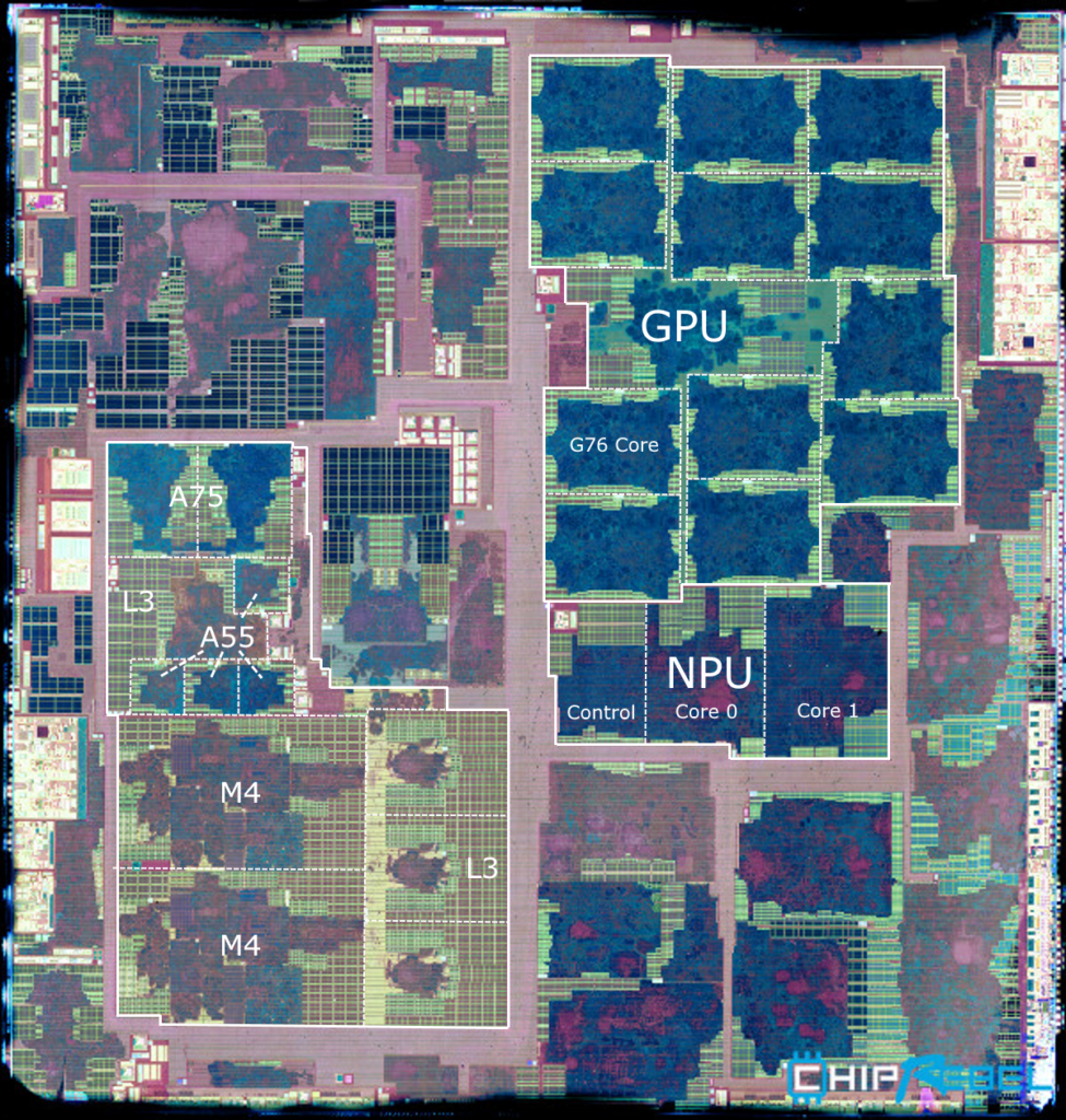
While ARM Cortex-A cores like the Cortex-A76 are used in high performance applications like smartphones, ARM also offers Cortex-M cores, which are low power, low cost microcontroller cores that are quickly becoming very popular in embedded systems.
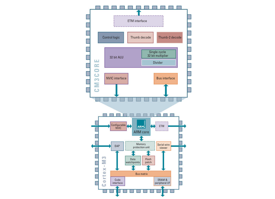
The STM32 line of MCUs from STMicroelectronics is possibly the most commonly used Cortex-M based family of microcontrollers.
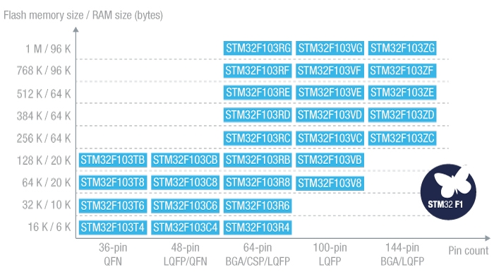
They feature free, open source toolchains and are pin to pin compatible within each family.
Components
Microcontroller
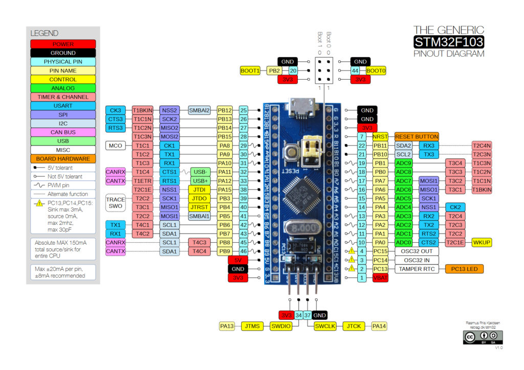
The STM32F103C8T6 is a speedy 72MHz ARM Cortex-M3 processor with 128KB of flash, 20KB Of SRAM and is available in the form of a QFN, or LQFP on a board that is more commonly known as the legendary “Blue Pill”
It has two, sixteen channel 12-bit ADCs, seven timers, three USART ports, two I2C interfaces, two SPI ports, a CAN interface, and USB 2.0 support.
Programmer
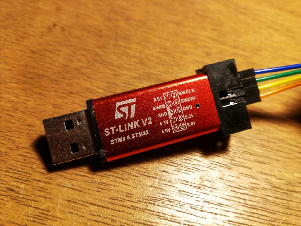
To flash your firmware onto the STM32 microcontroller, you’ll need a programmer like the ST-Link V2 clones which are cheap, and work perfectly.
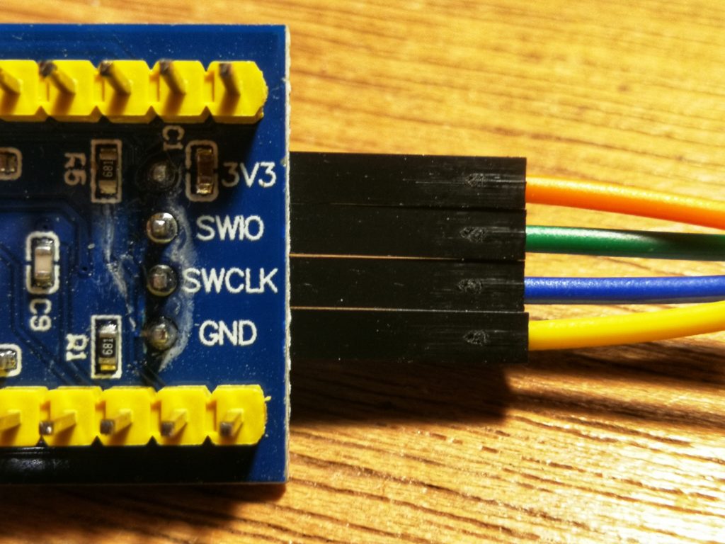
The STM32F103C8T6 uses a standard serial wire debug interface, so just connect the bidirectional data pins (SWDIO/SWIO) and clock signal pins (SWCLK) of the dev board to the corresponding pins on the ST-Link.
- 3.3V to 3.3V
- SWDIO to SWIO
- SWCLK to SWCLK
- GND to GND
Software Setup
- Setup the compiler
- Setup the firmware library
- Setup the programmer tool
- Use your favorite text editor/IDE
Setting up the cross compiler
First we’ll need to install a version of GCC that is compatible with embedded ARM microcontroller processors.
sudo apt install gcc-arm-none-eabi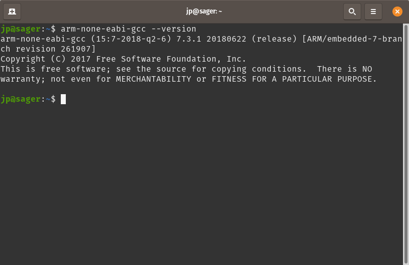
A cross compiler allows you to generate machine code for hardware that is different from the one you are currently using for writing your application.
Setting up the firmware library
We’ll use this environment, which includes both FreeRTOS and libopencm3 as a template.
git clone https://github.com/ve3wwg/stm32f103c8t6 stm32git submodule update --initRun make inside your new stm32 folder.
makeSetup the programmer tools
sudo apt install stlink-toolsNow check if your ST-LINK is detected.
st-info --probe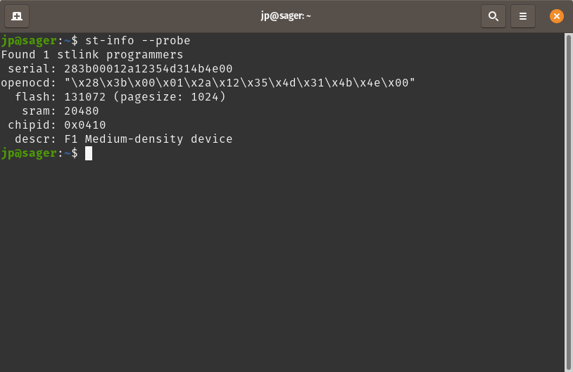
Code
/*
 * This file is part of the libopencm3 project.
 *
 * Copyright (C) 2009 Uwe Hermann <uwe@hermann-uwe.de>
 *
 * This library is free software: you can redistribute it and/or modify
 * it under the terms of the GNU Lesser General Public License as published by
 * the Free Software Foundation, either version 3 of the License, or
 * (at your option) any later version.
 *
 * This library is distributed in the hope that it will be useful,
 * but WITHOUT ANY WARRANTY; without even the implied warranty of
 * MERCHANTABILITY or FITNESS FOR A PARTICULAR PURPOSE.  See the
 * GNU Lesser General Public License for more details.
 *
 * You should have received a copy of the GNU Lesser General Public License
 * along with this library.  If not, see <http://www.gnu.org/licenses/>.
 */
#include <libopencm3/stm32/rcc.h>
#include <libopencm3/stm32/gpio.h>

static void
gpio_setup(void) {

	/* Enable GPIOC clock. */
	rcc_periph_clock_enable(RCC_GPIOC);

	/* Set GPIO8 (in GPIO port C) to 'output push-pull'. */
	gpio_set_mode(GPIOC,GPIO_MODE_OUTPUT_2_MHZ,
		      GPIO_CNF_OUTPUT_PUSHPULL,GPIO13);
}

int
main(void) {
	int i;

	gpio_setup();

	for (;;) {
		gpio_clear(GPIOC,GPIO13);	/* LED on */
		for (i = 0; i < 1500000; i++)	/* Wait a bit. */
			__asm__("nop");

		gpio_set(GPIOC,GPIO13);		/* LED off */
		for (i = 0; i < 500000; i++)	/* Wait a bit. */
			__asm__("nop");
	}

	return 0;
}
The miniblink example code sets up the GPIO connected to the LED on the STM32 Blue Pill board, as an output, to drive the LED. The delay is generated through some in line assembly. The assembly instruction “nop” or “no op”, which means no operation, commands the CPU to do nothing for that instruction cycle.
Flashing the firmware
Run the st-flash package to write your code to the appropriate location in flash memory.
In the case of the STM32, 0x08000000 is actually an alias of 0x00000000, which is the beginning of program memory for all STM32 cores.
st-flash write $PATH_TO_FILE/miniblink.bin 0x8000000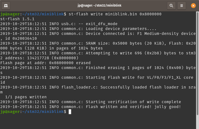
You should see this cheeky message as output on the terminal when you’ve successfully written your firmware to flash memory using your ST-Link.
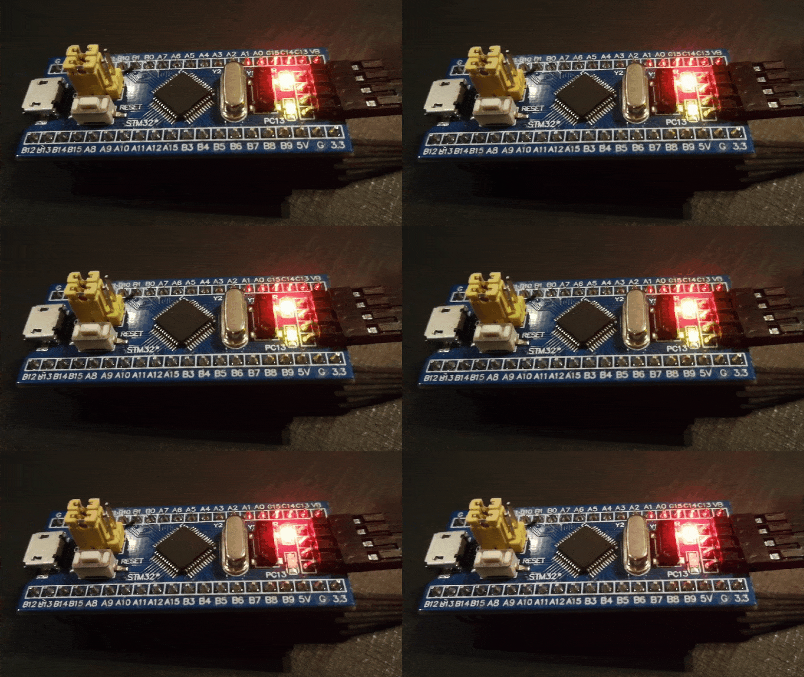
Congratulations! You’ve successfully taken your first step into developing on ARM microcontrollers.
Good luck, and stay creative!


