
Wiring
The sensor node connections
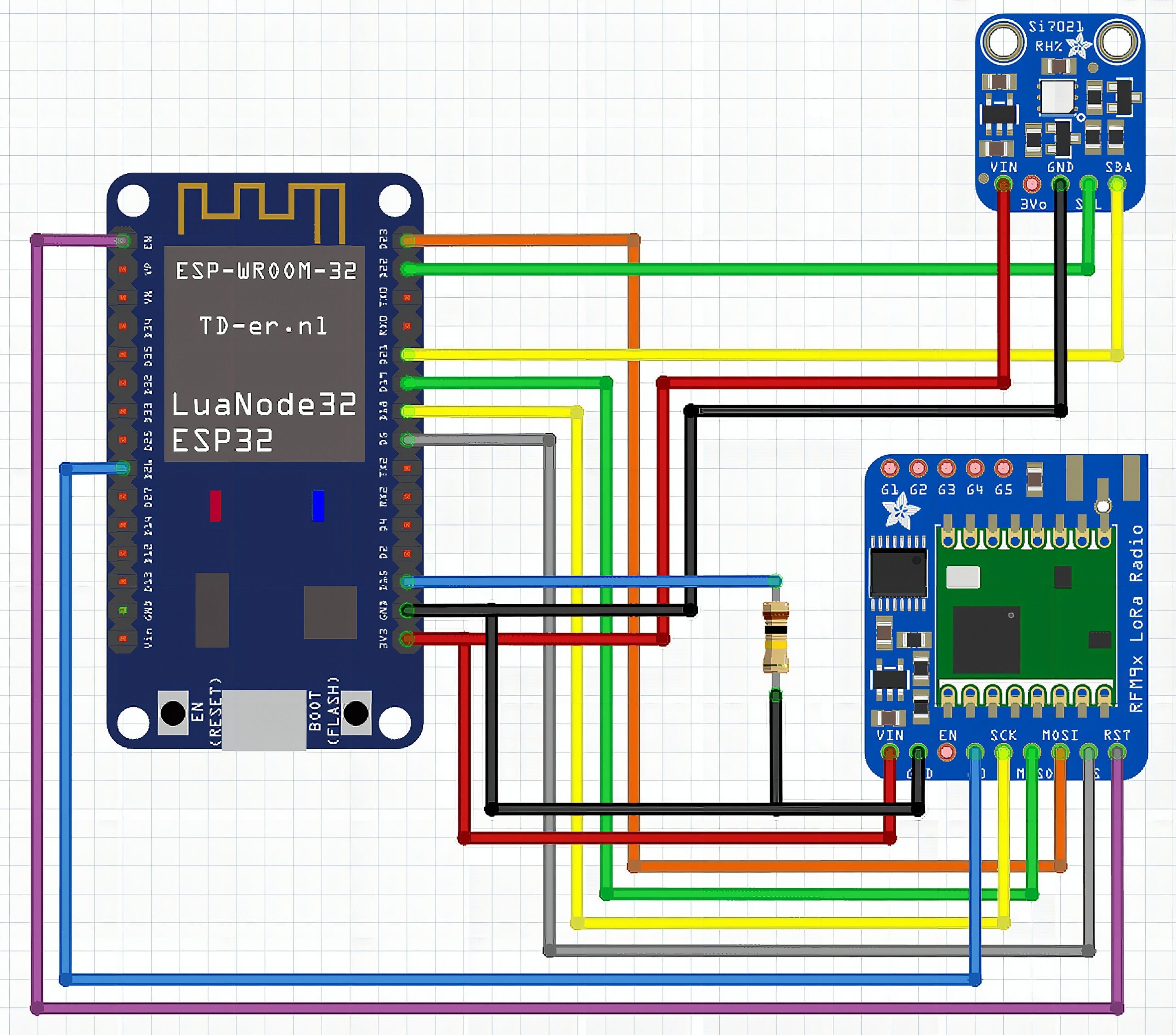
The LoRa module connections:
- The power pins (VIN and GND) are connected to the ESP32s power pins. The RFM95 modules work well with both 3.3V and 5V.
- The SPI pins SCK, MISO, MOSI and CS of the LoRa module are connected to the default VSPI pins of the ESP32, GPIOs 18, 19, 23 and 5.
- The DIO0 pin (G0 in the Fritzing diagram) is the interrupt signal of the LoRa module. You can connect it to any GPIO of the ESP32 that works as an input, I chose GPIO 26.
- The RST pin could be connected to an GPIO as well to be able to manually reset the LoRa module. But on the module I used (see the very first picture), there was no access to this pin, because the LoRa module was integrated on the ESP32 board. So here it is only connected to the EN pin of the ESP32, which is the ESP32s reset pin.
- The sensor connections:
- The I2C pins from the sensor are connected to the default I2C pins of the ESP32 (GPIO21 = SCL, GPIO22 = SDA).
- The power pins from the sensor are connected to 3.3V and GND of the ESP32.
- Others:
- One 100k ohm resistor is connected from GPIO15 to GND
The sensor connections:
- The I2C pins from the sensor are connected to the default I2C pins of the ESP32 (GPIO21 = SCL, GPIO22 = SDA).
- The power pins from the sensor are connected to 3.3V and GND of the ESP32.
Others:
- One 100k ohm resistor is connected from GPIO15 to GND
Required libraries
For the sensor nodes only 2 libraries are required. All libraries are available through the library manager of ArduinoIDE.
RadioLib
Different to the first tutorial I switched to the RadioLib library. There are 2 reasons for the switch.
1) RadioLib supports both LoRa chips that I used, the SX127x and the SX126x. The RadioHead library used before doesn’t support the SX126x chips.
2) RadioLib has an important function called CAD (channel activity detection). We will need this function to make sure that we do not send LoRa packages from two nodes at the same time. Sending on the same frequency from two nodes at the same time would result in a destroyed package.

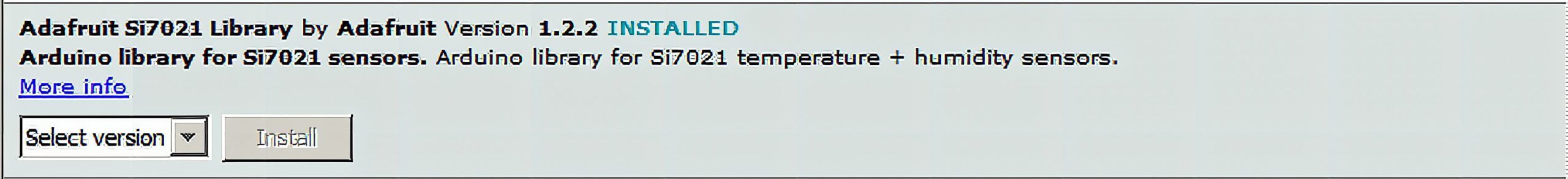
Adafruit SI7021
This library is used to read temperature and humidity from the Si7021 sensors. If you use a different sensor, you have to change this to a library matching your sensor.
The sensor node software
Before just giving you the full code, I want to take out some snippets and explain what they do. You might be surprised as well that the loop() is complete empty. That is because the software flow will never reach the loop.
As said before, the sensor nodes are supposed to run on battery only. To achieve a usable battery life time with an ESP32, you cannot have it running on full speed all the time. That would drain the battery very fast.
Instead we are using a feature of the ESP32 that is called deep-sleep. During deep-sleep all power-hungry peripherals like WiFi, Bluetooth and even the CPU core of the chip are powered down. Only a ULP processor is still powered and running. ULP means UltraLowPower. This ULP processor has limited functionality and runs very slow. It can be used to wake up the ESP32 from deep-sleep after a programmable time. And this is what we will use. There are other possibilities to wake up the ESP32 from deep sleep, but that might be for another learning blog.
What we want to do is to run a view functions after the ESP32 comes out of power-up or deep-sleep:
– Initialize LoRa
– Initialize the temperature and humidity sensor
– Read the sensor values
– Send the sensor values over LoRa
– Shutdown LoRa and send the LoRa chip into sleep mode
– Send the ESP32 into deep-sleep for 30 seconds
All of this happens in the setup() function. The loop() function is never reached, because we go into deep-sleep before the loop() is ever started.
Choose the SPI peripheral
The ESP32 has two SPI interfaces, called VSPI and HSPI. They have different default GPIOs. Depending to which SPI you have connected the LoRa module, the initialization of the RadioLib class looks different
// Using VSPI and a SX1262 module
SPIClass *loraSPI = new SPIClass(VSPI);
// NSS DIO1 DIO2 BUSY
SX1262 lora = new Module(5, 26, -1, 25, *loraSPI); // Using HSPI and a SX1276 (RFM95W) module
SPIClass *loraSPI = new SPIClass(HSPI);
// NSS DIO0 DIO1
SX1276 lora = new Module(16, 26, 33, *loraSPI);
As you can see, to specify the SPI bus used, we define a pointer to the SPI class giving a parameter that defines to use HSPI or VSPI. Then when initializing the RadioLib class, we give the SPI pointer as a parameter.
The other parameters set the other control lines between the ESP32 and the LoRa module. They are different for the SX1276 and the SX1262.
Initializing the LoRa module
The initialization using the RadioLib class is different to what we saw in RadioHead library. Here we give 4 parameters (out of many more, check the library to see the options) to start all LoRa modules with the same settings. Here we chose 868.0MHz as base frequency, a bandwidth of 125kHz, a spreading factor of 8 and a coding rate of 4/5. What does all of this mean? I don’t want to go into these details here, because I want to concentrate on the principal usage of LoRa. But as mentioned in my other blog, check out the technical paper of the LoRa Alliance.
// Initialize LoRa int state = lora.begin(868.0, 125.0, 8, 5);
Set the ESP32 to deep sleep and wake up every 30 seconds
The deep sleep function expects to setup a wake up timer before going into deep sleep. Now we could set this timer to 30 seconds, but then the sensor data would not be sent every 30 seconds, but every 31, 32 or even 35 seconds. Why? Because after waking up, we have to do the initialization, reading the sensors and sending the data package over LoRa.
This takes some time, I measured between 100ms and 2 seconds. The time depends mainly on the availability of the LoRa channel. So before going into deep-sleep we have to set the wake up timer to a value of 30 seconds – runtime since wake up. To do this we save the time of wake up and calculate the next wake up time by subtracting the run-time from the 30 seconds. In the code this looks like
// Conversion factor for micro seconds to milli seconds
#define uS_TO_mS_FACTOR 1000
// Time ESP32 will go to sleep (in milliseconds)
long sleepForMillis = 30000;
// The wakeup time
time_t wakeup; void setup()
{ // Remember the wake up time wakeup = millis();..... // Go back to bed time_t awakeTime = millis() - wakeup; esp_sleep_enable_timer_wakeup((sleepForMillis - awakeTime) * uS_TO_mS_FACTOR); esp_deep_sleep_start();
Make sure that LoRa packages are not colliding
As said before, you have to make sure that the node is sending a package while another node is transmitting. To this, RadioLib has a function called scanChannel().
This function is not a software function, but it is embedded in the Semtech SX chips as CAD (Channel Activity Detection). When starting the scanChannel, the SX LoRa chip will listen to the selected frequency (= channel) to see if any other node on this channel is active sending. The result is then returned. If a channel activity is detected, the node must not start sending its package, but instead wait and check again for a free slot to send its package.
If you use a lot of sensor nodes or if there are other LoRa devices around using the same frequency (channel), it might take some time before your node finds a free slot. In this code example we try 20 times to find a sending slot. This equals to ~4000 milliseconds before we give up to send. It might as well happen that the sending still fails (due to collisions), so we try 3 times to send the package before we give up.
uint8_t retryCAD = 0; uint8_t retrySend = 0; bool sendSuccess = false; while (!sendSuccess) { time_t loraTime = millis(); // Check 200ms for an opportunity to send while (lora.scanChannel()!= CHANNEL_FREE) { retryCAD++; if (retryCAD == 20) { // LoRa channel is busy too long, give up Serial.println("Channel is too busy, give up"); retrySend++; break; } } Serial.printf("CAD finished after %ldms tried %d timesn", (millis() - loraTime), retryCAD); if (retryCAD < 20) { // Channel is free, start sending loraTime = millis(); int status = lora.transmit((uint8_t *)dataMsg, sizeof(dataMsg)); Serial.printf("Transmit finished after %ldms with status %dn", (millis() - loraTime), status); if (status == ERR_NONE) { sendSuccess = true; } else { retrySend++; } } if (retrySend == 3) { Serial.println("Failed 3 times to send data, giving up"); sendSuccess = true; } }As you might understand now, there is no guarantee that your sensor node is able to send his data every 30 seconds. Of course you can try to increase the number of retries, but that will definitely cost you battery lifetime.
Define the data packages
To make sure the LoRa gateway knows
a) that the received data package is from a sensor it is supposed to listen to and not from another persons LoRa node
b) which sensor sent the data
To achieve this, I defined a structure for the data package which looks like this:
1 byte sensor ID – 0 to 255 for 256 possible sensor nodes
1 byte magic byte – always 0xAA
4 bytes for the data – can be any kind of sensor data
So the gateways has 2 identifiers to know that the package is from a known sensor node.
a) The data package is 6 bytes long
b) The data package contains the magic byte (which is 0xAA)
This is not bullet-proof, it still can happen that a package from a foreign LoRa node has 6 bytes length and the second byte is 0xAA. But it should be enough for this tutorial. To make it more secure, you can extend the package size and for example put more magic bytes into the structure, e.g. one magic byte between each of the sensor data bytes.
Some tips how to save more battery
While we have the sensor node most of the time in deep-sleep, there are a few more things that you can do to reduce power consumption.
1) Most important!
Remove the power LED from your ESP32 board. Basically every ESP32 breakout board has a LED that is directly connected to the 3.3V. While this doesn’t matter if you are supplying from a USB charger, it matters a lot if you are supplying from a battery. The LED draws some mA all the time from the battery and that is not what we want. De-solder or clip-off the power LED from your battery supplied board to get better battery life-times.
2) What you might not have known
Enabling and sending data over the serial port (USB in most cases) draws current from you battery, even if there is no receiving port connected to it.
So to save more battery, remove all serial output from the code, don’t even initialize the serial port!
3) Something I am sure you didn’t know
Everytime you power up or reset your ESP32 you can see on the serial monitor some output like
rst:0x5 (DEEPSLEEP_RESET),boot:0x13 (SPI_FAST_FLASH_BOOT)
configsip: 0, SPIWP:0xee
clk_drv:0x00,q_drv:0x00,d_drv:0x00,cs0_drv:0x00,hd_drv:0x00,wp_drv:0x00
mode:DIO, clock div:1
load:0x3fff0018,len:4
load:0x3fff001c,len:1100
load:0x40078000,len:9232
load:0x40080400,len:6400
entry 0x400806a8
This is the debug output of the bootloader over serial, which (reason above) we also don’t want. But how to get rid of it.
There is a simple trick and you can find it when you go through the data-sheet of the ESP32. Some of the GPIO’s of the ESP32 have special functions during boot-up and one of them is GPIO15. If you pull-down GPIO15 during power-up or reset or return from deep-sleep, the bootloader will surpress these bootloader messages over serial. This might not save much, but we are hunting here for every mAh that we can reduce.
And here is the complete code including the sensor reading (This code is for the Sparkfun ESP32 with the RFM95 module):
#include <Arduino.h>
#include <WiFi.h>
#include <RadioLib.h> #include "Adafruit_Si7021.h" SPIClass *loraSPI = new SPIClass(HSPI);
// NSS DIO1 DIO2 BUSY
SX1276 lora = new Module(16, 26, 33, *loraSPI); // Define a LED port if not already defined
#ifndef LED_BUILTIN
// Change this to the GPIO connected to an LED
#define LED_BUILTIN 17
#endif /** SI 7021 sensor */
Adafruit_Si7021 sensor = Adafruit_Si7021(); // Conversion factor for micro seconds to seconds
#define uS_TO_mS_FACTOR 1000
// Time ESP32 will go to sleep (in milliseconds)
long sleepForMillis = 30000;
// The wakeup time
time_t wakeup; // The Data message will be sent by the node
uint8_t dataMsg[6];
// Tracks the time stamp of last packet received
long timeSinceLastPacket = 0; // Id of the node that sent a package
uint16_t nodeId = 0; // Temperature integer part
uint8_t tempInt;
// Temperature fraction part
uint8_t tempFrac;
// Humidity integer part
uint8_t humidInt;
// Humidity fraction part
uint8_t humidFrac; void goToSleep(void)
{ time_t sendToSleep = millis(); // Send the LoRa module to sleep int status = lora.sleep(); Serial.printf("Set Lora to sleep took %ldms with result %dn", (millis() - sendToSleep), status); Serial.printf("Sleeping after %ldmsn", (millis() - wakeup)); // Go back to bed time_t awakeTime = millis() - wakeup; esp_sleep_enable_timer_wakeup((sleepForMillis - awakeTime) * uS_TO_mS_FACTOR); esp_deep_sleep_start();
} void setup()
{ WiFi.mode(WIFI_OFF); wakeup = millis(); // Start serial communication Serial.begin(115200); // Initialize LoRa int state = lora.begin(868.0, 125.0, 8, 5); if (state!= ERR_NONE) { Serial.printf("nLoRa begin failed %dnn", state); } lora.setOutputPower(17); pinMode(LED_BUILTIN, OUTPUT); // Show we are awake digitalWrite(LED_BUILTIN, LOW); Serial.println("====================================="); Serial.println("LoRa sensor node test"); Serial.println("====================================="); // Initialize SI7021 temperature sensor if (!sensor.begin()) { Serial.println("Did not find Si7021 sensor!"); } // Get the sensor values float sensTemp = sensor.readTemperature(); float sensHumid = sensor.readHumidity(); if ((sensTemp == NAN) || (sensHumid == NAN) || (sensTemp == 255.255) || (sensHumid == 255.255)) { // Error reading the sensor, try one more time float sensTemp = sensor.readTemperature(); float sensHumid = sensor.readHumidity(); if ((sensTemp == NAN) || (sensHumid == NAN)) { // Second reading failed as well, give up Serial.println("Could not read sensor data, skip sending"); goToSleep(); } } tempInt = (uint8_t)sensTemp; tempFrac = (uint8_t)((sensTemp - tempInt) * 100); humidInt = (uint8_t)sensHumid; humidFrac = (uint8_t)((sensHumid - humidInt) * 100); Serial.print("Temp "); Serial.print(tempInt); Serial.print("."); Serial.println(tempFrac); Serial.print("Humid "); Serial.print(humidInt); Serial.print("."); Serial.println(humidFrac); Serial.printf("Finished reading sensor after %ldmsn", (millis() - wakeup)); dataMsg[0] = 0x00; dataMsg[1] = 0xAA; dataMsg[2] = tempInt; dataMsg[3] = tempFrac; dataMsg[4] = humidInt; dataMsg[5] = humidFrac; uint8_t retryCAD = 0; uint8_t retrySend = 0; bool sendSuccess = false; while (!sendSuccess) { time_t loraTime = millis(); // Check 200ms for an opportunity to send while (lora.scanChannel()!= CHANNEL_FREE) { retryCAD++; if (retryCAD == 20) { // LoRa channel is busy, give up Serial.println("Channel is too busy, give up"); retrySend++; break; } delay(100); } Serial.printf("CAD finished after %ldms tried %d timesn", (millis() - loraTime), retryCAD); if (retryCAD < 20) { // Channel is free, start sending loraTime = millis(); int status = lora.transmit((uint8_t *)dataMsg, sizeof(dataMsg)); Serial.printf("Transmit finished after %ldms with status %dn", (millis() - loraTime), status); if (status == ERR_NONE) { sendSuccess = true; } else { retrySend++; } } if (retrySend == 3) { Serial.println("Failed 3 times to send or receive ACK, giving up"); sendSuccess = true; } } // All done, go back to sleep and save battery goToSleep();
} void loop()
{ // We will never get here
}
Frequently Asked Questions
[faq] [faq_q]What is a typical battery life for a LoRa sensor node?[/faq_q] [faq_a]1-3 years on a single 2500 mAh 18650 if the node wakes every 15-30 minutes, sends a small packet, then deep-sleeps. Faster reporting drops this to weeks or months.[/faq_a] [faq_q]Why use LoRa for sensor nodes instead of Wi-Fi?[/faq_q] [faq_a]Range and battery. LoRa reaches kilometers; Wi-Fi reaches meters. LoRa transmits in milliseconds at a few mA; Wi-Fi takes seconds at 80+ mA. For battery-powered remote sensors, LoRa wins on both.[/faq_a][faq_q]Do I need a LoRa gateway for the sensor node to work?[/faq_q] [faq_a]For most use cases, yes. The sensor sends data, and a gateway needs to receive it. Two nodes can also talk directly point-to-point in non-LoRaWAN mode.[/faq_a][faq_q]What sensors are common on LoRa nodes?[/faq_q] [faq_a]Temperature/humidity (DHT22 or SHT31), soil moisture, water level, door open/close, and reed switches. Anything with a low-current sensor and infrequent reporting fits the LoRa profile.[/faq_a][faq_q]Can the sensor node run on solar power?[/faq_q] [faq_a]Yes. A small 5V solar panel (1-2W) plus a TP4056 charging board and 18650 LiPo runs a LoRa sensor node indefinitely as long as it gets a few hours of sun a day.[/faq_a][/faq]Frequently Asked Questions
What does this Battery powered LoRa sensor node tutorial cover?
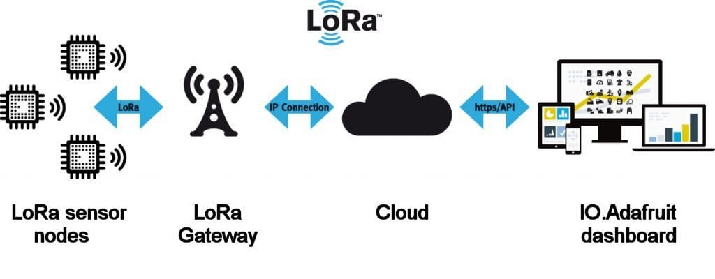
Part #1 – The sensor nodes In my other post I made an introduction to Long Range (LoRa) communication .
What's the working voltage of the Battery powered LoRa sensor node?
Check the Sample Code section for the exact pinout — most maker-grade sensors run on 3.3V or 5V. Wire VCC to the matching rail, GND common with your MCU, data to a digital or analog pin.
Why does the Battery powered LoRa sensor node read garbage or saturated values?
Three usual causes: wrong voltage rail, missing pull-up resistor on I2C lines (4.7k–10k to VCC), or a floating data pin. Double-check wiring against the diagram, then probe with a multimeter.