

Wiring
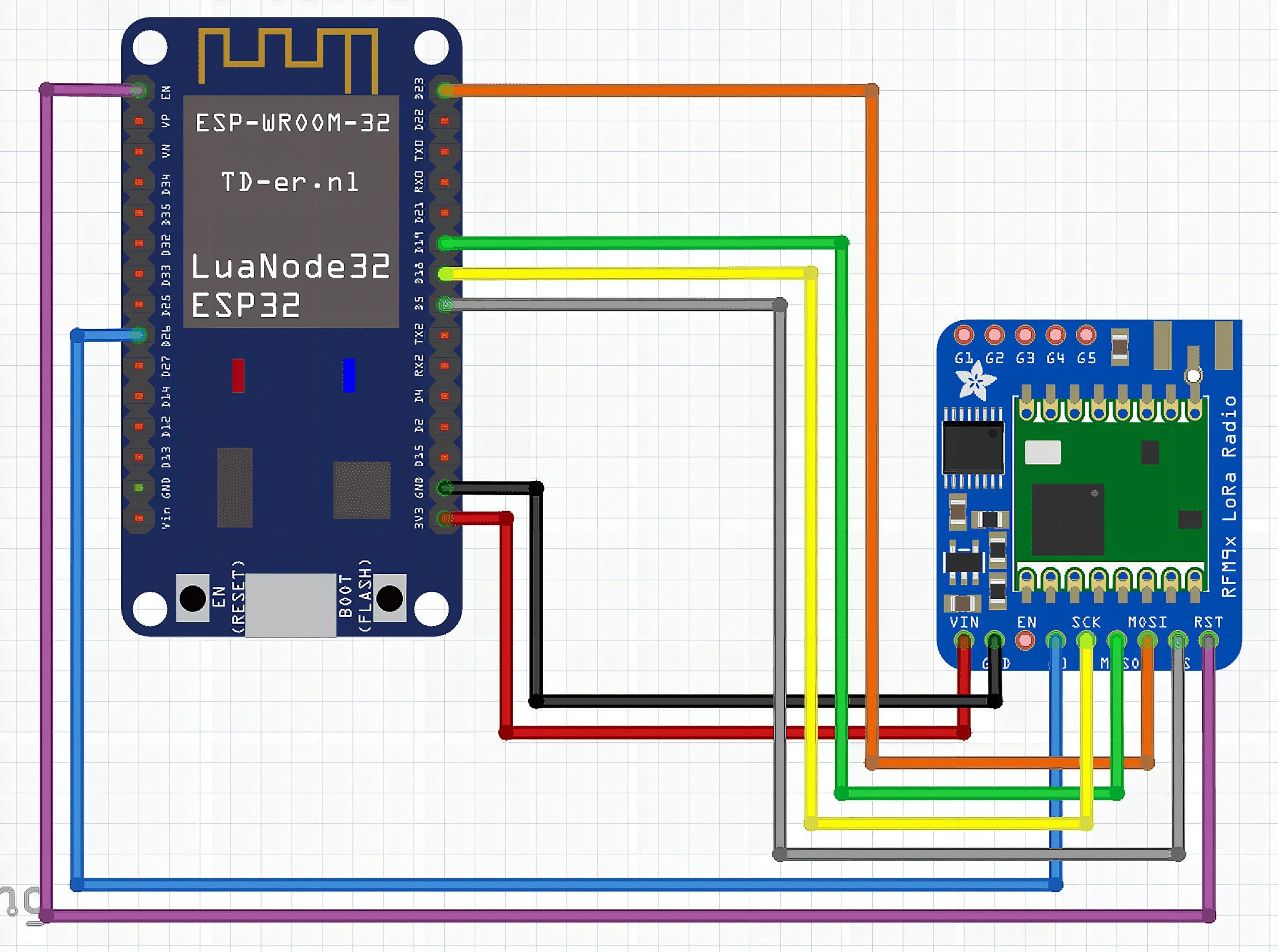
The connections
- The power pins (VIN and GND) are connected to the ESP32s power pins. The RFM95 modules work well with both 3.3V and 5V.
- The SPI pins SCK, MISO, MOSI and CS of the LoRa module are connected to the default VSPI pins of the ESP32, GPIOs 18, 19, 23 and 5.
- The DIO0 pin (G0 in the Fritzing diagram) is the interrupt signal of the LoRa module. You can connect it to any GPIO of the ESP32 that works as an input, I chose GPIO 26.
- The RST pin could be connected to an GPIO as well to be able to manually reset the LoRa module. But on the module I used (see the very first picture), there was no access to this pin, because the LoRa module was integrated on the ESP32 board. So here it is only connected to the EN pin of the ESP32, which is the ESP32s reset pin.
Libraries
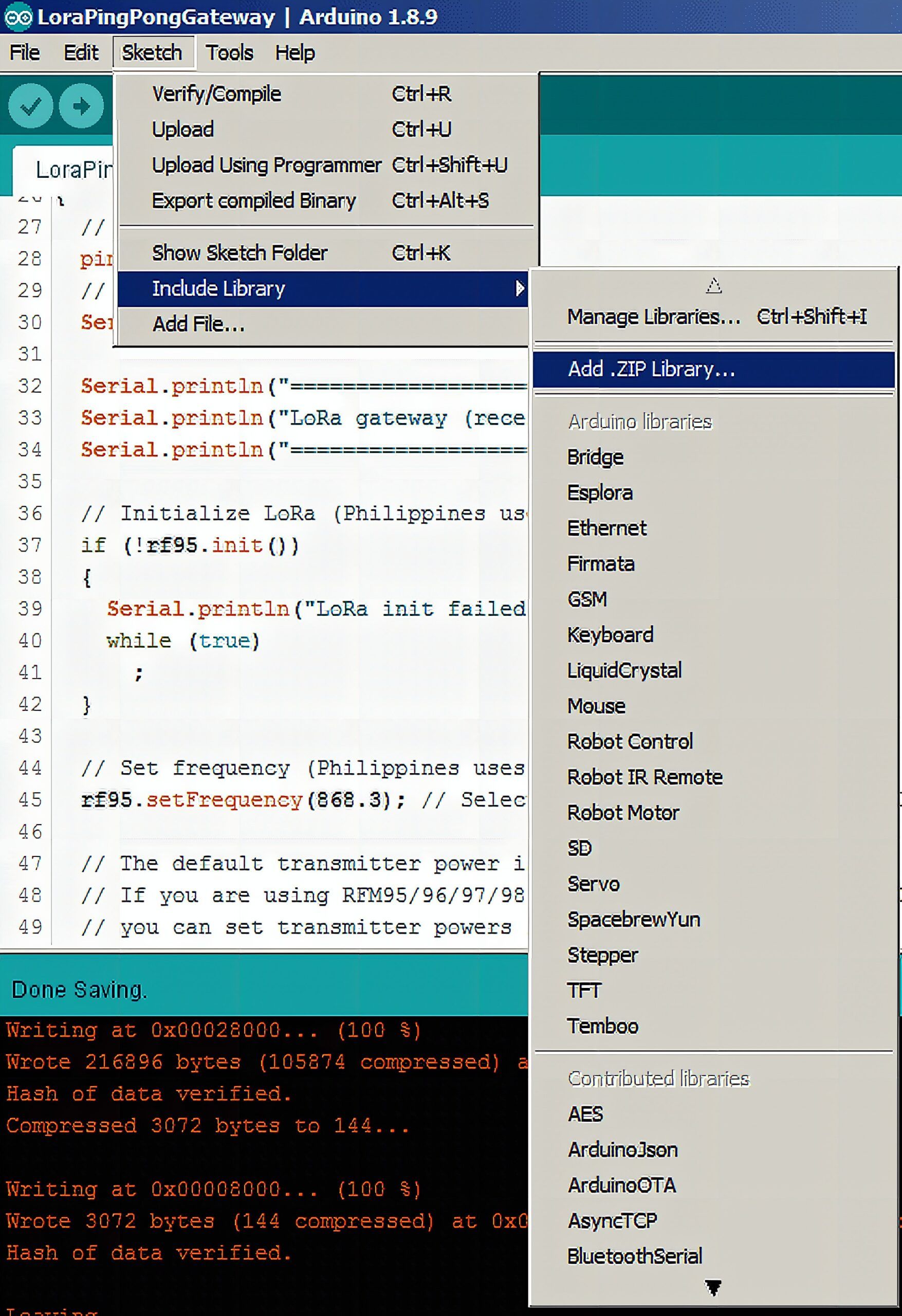
There is only library required in this tutorial, and that is the RadioHead library. I couldn’t find it in the ArduinoIDE library manager. So you have to download it from here (look for the  button). Save it on your harddisk and add it to ArduinoIDE by using Sketch->Include library->Add.ZIP library
The software
We will use two sketches, that are very similar. The difference is that the sketch LoraPingPongNode will start the communication by sending a data package (PING). The sketch LoraPingPongGateway is waiting to receive a data package and will response to it with another package (PONG). Nothing more is happening here, beside that on each module a LED is flashing while the two modules are able to communicate with each other. This is perfect if you want to make some range tests and don’t have a computer attached to the ESP32s to see the debug output.
The “node” sketch
#include <Arduino.h>
#include <RH_RF95.h> // Change this to the GPIO connected to the RFM95 SS pin
#define NSS 5
// Change this to the GPIO connected to the RFM95 DIO0 pin
#define DIO0 26 // Define a LED port if not already defined
#ifndef LED_BUILTIN
// Change this to the GPIO connected to an LED
#define LED_BUILTIN 17
#endif // Initialize the interface
RH_RF95 rf95(NSS, DIO0); // The Ping message will be sent by the node
char pingMsg[] = "PING";
// The Pong message will be sent by the gateway
char pongMsg[] = "PONG";
// Tracks the time stamp of last packet received
long timeSinceLastPacket = 0; void setup()
{ // Initialize the LED port pinMode(LED_BUILTIN, OUTPUT); // Start serial communication Serial.begin(115200); Serial.println("====================================="); Serial.println("LoRa node (sender) test"); Serial.println("====================================="); // Initialize LoRa if (!rf95.init()) { Serial.println("LoRa init failed. Check your connections."); while (true); } // Set frequency (Philippines uses same frequency as Europe) rf95.setFrequency(868.3); // Select the frequency 868.3 MHz - Used in Europe // The default transmitter power is 13dBm, using PA_BOOST. // Set Transmitter power to 20dbm. rf95.setTxPower(20, false);
} void loop()
{ Serial.println("Sending a PING"); rf95.send((uint8_t *)pingMsg, sizeof(pingMsg)); rf95.waitPacketSent(); // Now wait for a reply byte buf[RH_RF95_MAX_MESSAGE_LEN]; byte len = sizeof(buf); if (rf95.waitAvailableTimeout(2000)) { // Should be a reply message for us now if (rf95.recv(buf, &len)) { Serial.print("Got reply: "); Serial.println((char *)buf); Serial.print(" RSSI: "); Serial.println(rf95.lastRssi(), DEC); } else { Serial.println("Receive failed, is the Gateway running?"); } } else { Serial.println("No reply, is the Gateway running?"); } delay(500);
}
The “gateway” sketch
#include <Arduino.h>
#include <RH_RF95.h> // Change this to the GPIO connected to the RFM95 SS pin
#define NSS 5
// Change this to the GPIO connected to the RFM95 DIO0 pin
#define DIO0 26 // Define a LED port if not already defined
#ifndef LED_BUILTIN
// Change this to the GPIO connected to an LED
#define LED_BUILTIN 17
#endif // Initialize the interface
RH_RF95 rf95(NSS, DIO0); // The Ping message will be sent by the node
char pingMsg[] = "PING";
// The Pong message will be sent by the gateway
char pongMsg[] = "PONG";
// Tracks the time stamp of last packet received
long timeSinceLastPacket = 0; void setup()
{ // Initialize the LED port pinMode(LED_BUILTIN, OUTPUT); // Start serial communication Serial.begin(115200); Serial.println("====================================="); Serial.println("LoRa node (sender) test"); Serial.println("====================================="); // Initialize LoRa if (!rf95.init()) { Serial.println("LoRa init failed. Check your connections."); while (true); } // Set frequency (Philippines uses same frequency as Europe) rf95.setFrequency(868.3); // Select the frequency 868.3 MHz - Used in Europe // The default transmitter power is 13dBm, using PA_BOOST. // Set Transmitter power to 20dbm. rf95.setTxPower(20, false);
} void loop()
{ if (rf95.available()) { // Should be a message for us now uint8_t buf[RH_RF95_MAX_MESSAGE_LEN]; uint8_t len = sizeof(buf); if (rf95.recv(buf, &len)) { digitalWrite(LED_BUILTIN, HIGH); //Turn on status LED timeSinceLastPacket = millis(); //Timestamp this packet Serial.print("Got message: "); Serial.print((char *)buf); Serial.print(" RSSI: "); Serial.print(rf95.lastRssi(), DEC); Serial.println(); // Send a reply rf95.send((uint8_t *)pongMsg, sizeof(pongMsg)); rf95.waitPacketSent(); Serial.println("Sent a reply"); digitalWrite(LED_BUILTIN, LOW); //Turn off status LED } else Serial.println("Receive failed, is the node running?"); } //Turn off status LED if we haven't received a packet after 1s if (millis() - timeSinceLastPacket > 1000) { digitalWrite(LED_BUILTIN, LOW); //Turn off status LED timeSinceLastPacket = millis(); //Don't write LED but every 1s }
}
This software as it is doesn’t do anything useful, but it is the basic to understand how to connect the LoRa modules to an ESP32 and write some software to use it.
In my next learning blog we will connect sensors to the “node” ESP32, run it from battery and learn how we reduce the power consumption of the ESP32 to be able to run it over longer time without recharging the battery.
Once both modules are programmed and powered up, you will see a LED blinking on both modules and on the USB debug output you will see
=====================================
LoRa node (sender) test
=====================================
Got reply: PONG RSSI: -45
Got reply: PONG RSSI: -45
Got reply: PONG RSSI: -45
Got reply: PONG RSSI: -45
Got reply: PONG RSSI: -45
Got reply: PONG RSSI: -45
Got reply: PONG RSSI: -44
Got reply: PONG RSSI: -43
Got reply: PONG RSSI: -45
on the nodes output and
=====================================
LoRa gateway (receiver) test
=====================================
Found ESP32 define
Got message: PING RSSI: -18
Sent a reply
Got message: PING RSSI: -25
Sent a reply
Got message: PING RSSI: -26
Sent a reply
on the gateways output.
An important remark!
When you look to the LoRa modules, most of these cheap modules do not have an antenna connector. The instructions just say to solder a piece of copper wire to the antenna pin and you are ready to use it.
That is correct, but you should not expect to reach large ranges with such a solution. If you want to go for 500m, 1km or farther, you will need a proper tuned LoRa antenna. Most LoRa antennas are for a frequency range of 800MHz to 950MHz.
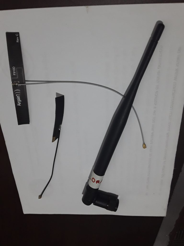
Interesting enough, the smaller flexible antennas shown on the picture have a better performance than the big one. It is all about how good the antennas are tuned for the frequency.
Frequently Asked Questions
What does this Long Range (LoRa) communication for devices that have no WiFi connection available tutorial cover?
Introduction to LoRa Usually we use WiFi, Bluetooth or GSM to connect our sensor devices with the world of IoT.
What's the working voltage of the Long Range (LoRa) communication for devices that have no WiFi connection available?
Check the Sample Code section for the exact pinout — most maker-grade sensors run on 3.3V or 5V. Wire VCC to the matching rail, GND common with your MCU, data to a digital or analog pin.
Why does the Long Range (LoRa) communication for devices that have no WiFi connection available read garbage or saturated values?
Three usual causes: wrong voltage rail, missing pull-up resistor on I2C lines (4.7k–10k to VCC), or a floating data pin. Double-check wiring against the diagram, then probe with a multimeter.