
When it comes to sensors and shields, two common serial connections available are SPI and I2C, but what exactly are they?
Serial Peripheral Interface (SPI)
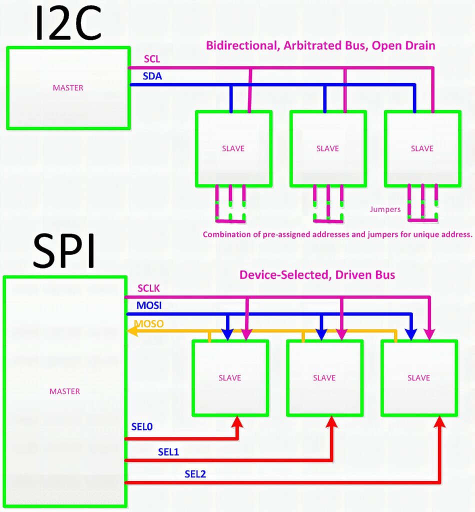
Serial Peripheral Interface is a serial interface bus that’s is commonly used to send data between microcontrollers and small peripherals such as sensors. SPI is a synchronous communication bus standard that is widely used due to how simple the implementation is and its high-speed data transfer. The usual setup when using SPI is a Master/Slave configuration wherein a single master controller can choose between one or more slave devices.
Connecting using SPI Protocol usually takes four wires, which is why it’s commonly referred to as a four-wire serial bus. The four wires are connected for the following purposes: SCLK, MOSI, MISO, and SS.
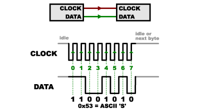
1. SCLK – Serial Clock signal. Since SPI is a synchronous connection, a clock signal is sent out from the master device and is received by the slave device in order to sync.
2. MOSI – Master Output Slave Input; this is the port where data transmitted from the master device to the slave device goes through.
3. MISO – Master Input Slave Output; the port where data is transmitted from slave device to master device.
4. SS – Slave Select (may also be referred to as Chip Select); This port is used to select which of the multiple slave devices are active. Although each slave device can share SCLK, MOSI, and MISO lines in a bus, each slave device requires a dedicated SS line, which
SPI is a straightforward interface method that is capable of achieving high data transfer speeds while operating with a relatively low power requirement. Although this type of interface allows for a wide range of possibilities, this configuration is limited by the number of slave nodes.
Inter-Integrated Circuit (I2C/IIC)
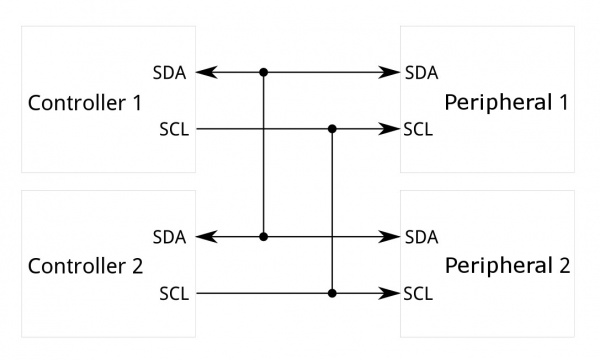
The Inter-Integrated Circuit Protocol is intended to allow multiple digital integrated circuits to communicate with one or more controllers with the need for only two wires.
Unlike Serial UART or SPI, I2C can support up to 1008 peripheral devices, while using only two wires, as well as allowing more than one controller in the bus. Keep note that the controllers can’t communicated with each other over the bus and have to take turns using the lines.
Implementing I2C is more complex than SPI, but simpler compared to asynchronous serial. I2C bus consists of two signals, the SCL and the SDA.
SDA – Clock Signal
SDA – Data Signal
Another difference of the I2C from UART and SPI connections is that the I2C bus drivers can pull corresponding signal line low but cannot drive the signal to a high. Through this, there is no contention in the system, wherein one device drives a line high while another pulls it low, resulting to potential damage to the drivers or a greater power dissipation.
For more information on SPI and I2C, please refer to the following links:
Rusin, M. (n.d.). Serial peripheral interface (SPI). Retrieved from: https://learn.sparkfun.com/tutorials/serial-peripheral-interface-spi/all
Sfiptownmaker. (n.d.). I2C. Retrieved from: https://learn.sparkfun.com/tutorials/i2c/all
Frequently Asked Questions
What does this SPI vs I2C tutorial cover?
When it comes to sensors and shields, two common serial connections available are SPI and I2C, but what exactly are they? Serial Peripheral Interface (SPI) Serial Peripheral Interface is a serial interface bus that’s is commonly used to send data between microcontrollers and small peripherals such as sensors.
What's the working voltage of the SPI vs I2C?
Check the Sample Code section for the exact pinout — most maker-grade sensors run on 3.3V or 5V. Wire VCC to the matching rail, GND common with your MCU, data to a digital or analog pin.
Why does the SPI vs I2C read garbage or saturated values?
Three usual causes: wrong voltage rail, missing pull-up resistor on I2C lines (4.7k–10k to VCC), or a floating data pin. Double-check wiring against the diagram, then probe with a multimeter.