Overview
Tony Stark is the quintessential engineer. To hackers, tinkerers and anyone infected with the propensity for building stuff – he represents the ultimate hero figure.

Using nothing but technical adeptness and raw engineering prowess, he arms himself with advanced technology to take on gods and galaxy conquering villains – and save the day.
This also makes him a very popular sight during cosplay conventions and comic cons. You’ll find out how to make his repulsors in this tutorial.
Components
Microcontroller
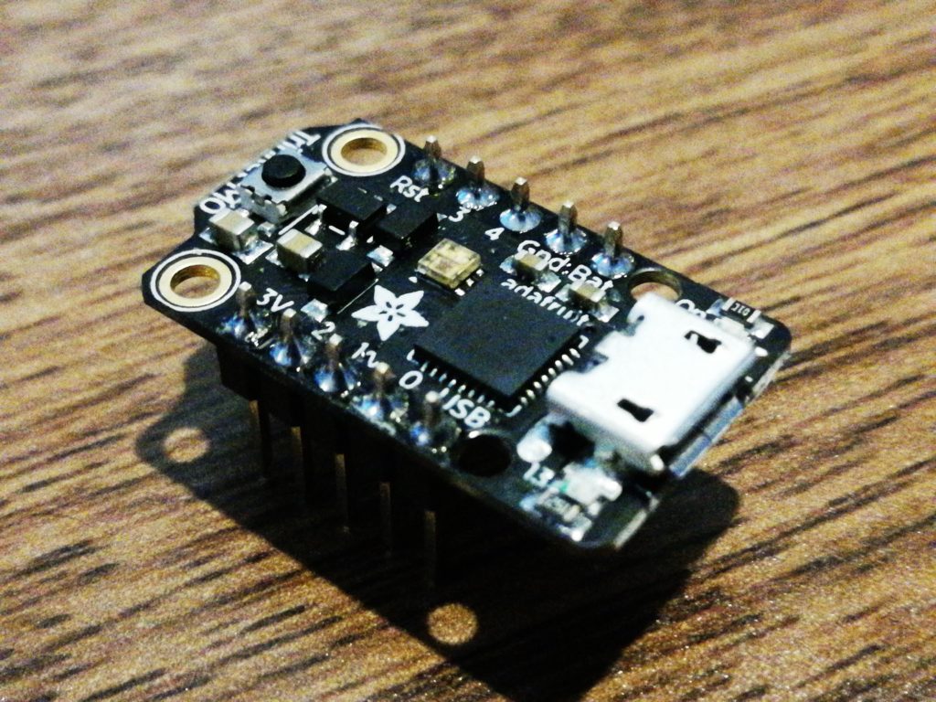
You’ll want a tiny, feasibly wearable microcontroller for this project. Since we won’t need a lot of pins, the Trinket M0 and its ATSAMD21 – a 32 bit, 48MHz processor is perfect for this situation.
While it comes with CircuitPython – as we’ve previously tackled, we’ll take advantage of the Arduino IDE compatibility of the Trinket M0 and go with the Arduino flavor of C/C++ this time around.
MPU-6050
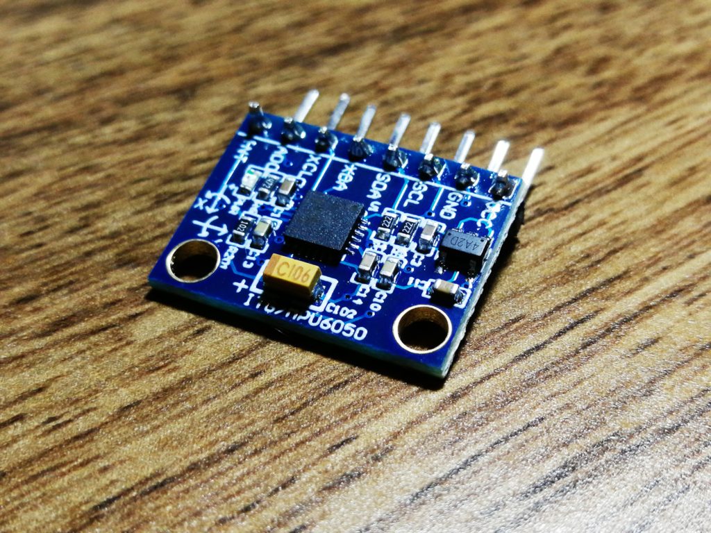
To sense the orientation of your fingers, you will need at least one Inertial Measurement Unit (IMU). The MPU-6050 is a popular, low cost IMU breakout board that’s cheap and plenty accurate for this task.
An IMU is a combination of an accelerometer and a gyroscope on a single device, using sensor fusion techniques to compensate for the weaknesses of each sensor, resulting in fairly accurate orientation sensing.
Neopixel Ring
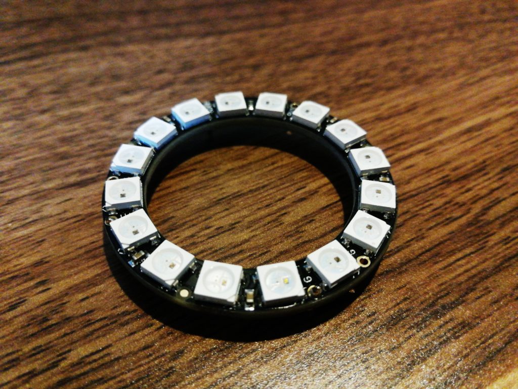
Adafruit’s ever prominent string of WS2812 LEDs, called “Neopixels”, are a staple of more colorful electronic projects. These are serially addressable RGB LEDs – which means you can control them with just a single data signal going through an entire chain of LEDs.
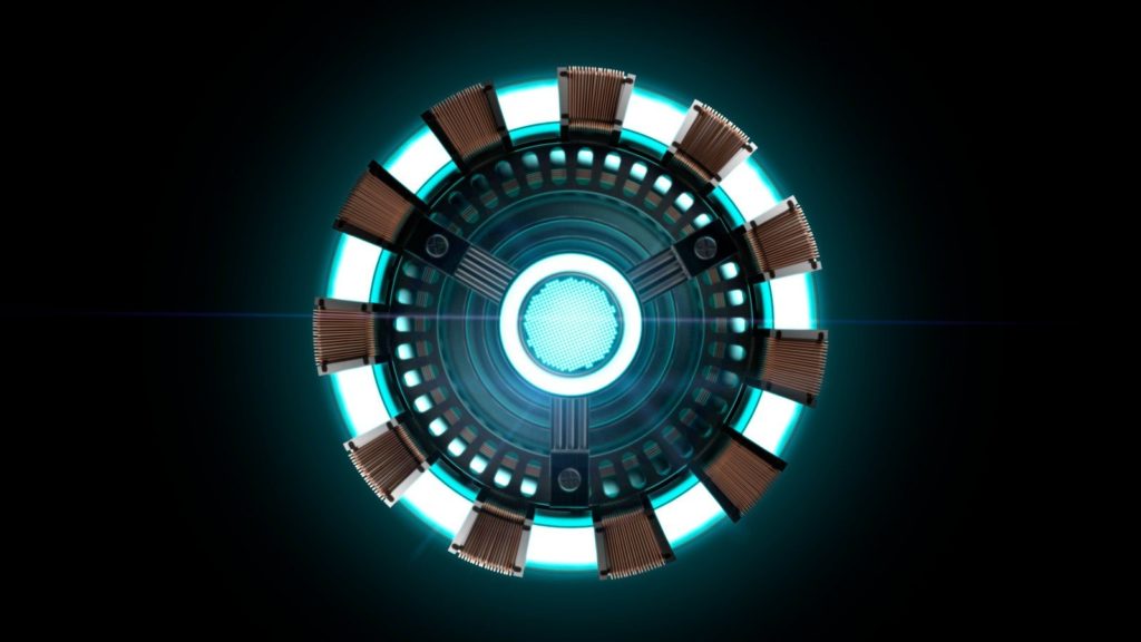
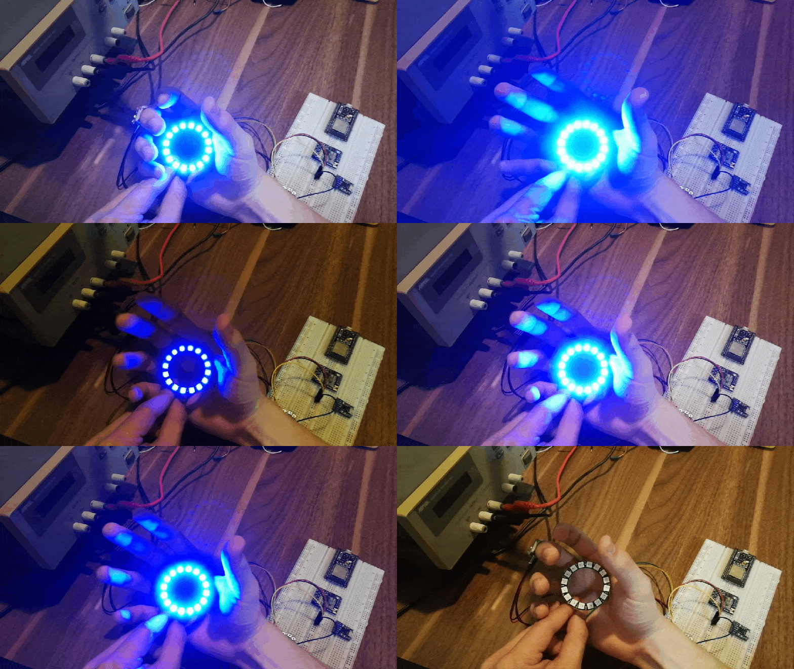
We’re using a ring which consists of 16 on board RGB LEDs, which conveniently enough – looks a lot like Tony Stark’s Arc Reactor.
Wiring
Power
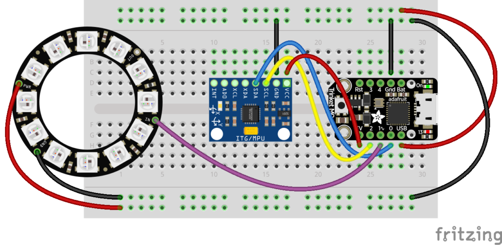
The Neopixel ring runs on 5V, so you’ll want to connect the V+ pin of the ring to the USB pin of the Trinket, offering 5V from your computer’s USB port or a power bank.
You can run the Neopixel on lower voltages, at the cost of decreased brightness.
The G or ground pin of the Neopixel ring should be connected to the ground pin of the Trinket M0.
The MPU-6050 module runs nominally on 3.3V, so you can use the 3V pin of the Trinket M0 to provide power to the module.
Signals
The single data signal coming out of the Trinket M0, pin 1 in our case, is hooked up straight into the Data In pin of the Neopixel ring.
You can opt to chain Neopixel rings or strips together using the Data Out pin on the Neopixel ring, as long as you have enough power to drive all the Neopixels.
The IMU uses I2C, so you’ll want to connect the Serial Data Line (SDA) and Serial Clock Line (SCL) of the MPU-6050 to the SDA and SCL pins of the Trinket M0.
The Trinket M0 uses pin 0 for SDA and pin 2 for SCL, so connect these to their respective counter parts on the MPU-6050.
You can opt to use jumper wires to connect the power and signal pins to the MPU-6050 so you can attach it to your finger – decoupled from the rest of the circuit.
Libraries
Here are the libraries you would want to have installed to get these devices up and running quickly.
Go to Sketch->Include Library->Manage Libraries to find these libraries.
Software Setup
To use the Arduino IDE to program a Trinket M0, you’re going to need to add support for the Trinket M0 to the board manager of the Arduino IDE. You can accomplish this by:
- Open Boards Manager from Tools > Board menu and install the Arduino SAMD boards entry.
- Still in the Boards Manager, install the Adafruit SAMD boards entry from the board manager.
- In Tools > Board, choose the Trinket M0 as your device.
The NUMPIXELS macro defines how many RGB LEDs or Neopixels are on your ring, you would change this if you had more or less than 16.
We’ll use pin 1 on our Trinket M0 to drive the data signal for the Neopixel ring.
Code
#include <Adafruit_NeoPixel.h>
#include <MPU6050_tockn.h>
#include <Wire.h>

MPU6050 mpu6050(Wire);

/*Define which pin you want to use for your ring*/
#define PIN        1

/*Define the number of RGB LEDs you have on your ring*/
#define NUMPIXELS 16

Adafruit_NeoPixel pixels(NUMPIXELS, PIN, NEO_GRB + NEO_KHZ800);

void setup() {

  Wire.begin();

  /*/Initialize the IMU*/
  mpu6050.begin();
  mpu6050.calcGyroOffsets(true);

  /* Initialize the Neopixels */
  pixels.begin();
  pixels.clear();
}

void loop() {
  mpu6050.update();

  /*Retrieve angle data and map it to the brightness level of the RGB LEDs*/
  int angle_x = mpu6050.getAngleX();
  angle_x = constrain(angle_x,-180,-40);
  int brightness = map(angle_x,-40,-180,0,255);

    for(int i=0; i<NUMPIXELS; i++) {

      /*Set R,G and B values - we'll tap blue for our Arc Reactor*/
      pixels.setPixelColor(i, pixels.Color(0, 0 , brightness));

      /*Update the Neopixel Ring with the new color value*/
      pixels.show();
    }
}
That’s all folks!
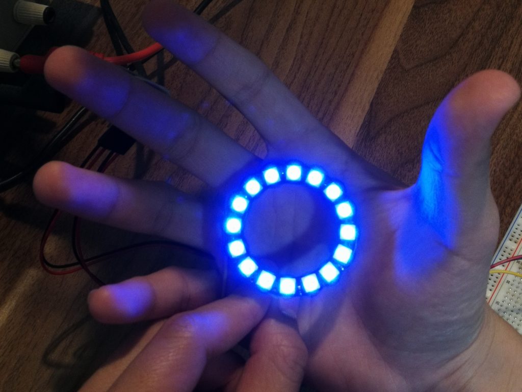
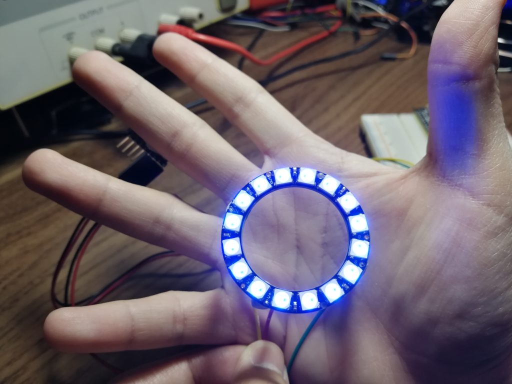
You’ve learned how to use an IMU to detect orientation and build yourself an Iron Man style repulsor along the way.
You can use the same method to build yourself an arc reactor that responds to the orientation of your fingers – daisy chain a couple of repulsors and you have yourself part of the iron man suit!
Making the 3D printed titanium alloy armor is the tough part.
Good luck, and stay creative!

