
Quite often, we want to place our sensors at locations where we have no access to a power outlet. The obvious solution is to add some solar panels and batteries to your project to make it run 24h / 7 days a week without the need to recharge it.
There are active solar charger breakouts available to connect your electronics to a battery and a solar panel, like the CN3065 Mini USB Solar Lithium Charger Board Module or the USB / DC / Solar Lithium Ion/Polymer charger v2.
But what if you use a controller board that already has a battery charger and battery connector on-board, like the Adafruit Feather series? Then why invest in a new charger board and voltage booster to charge your battery?
Simple Solar panel to 5V converter.
Here is a solution that requires only one cheap breakout board to use a solar panel to supply your micro-controller board with 5V and make use of the integrated battery charger component. The simple solution is to use a Step-Up-Down voltage converter, in this case, the DC-DC Automatic Step Up-down Power Module 3~15V to 5V 600mA.
The voltage converter
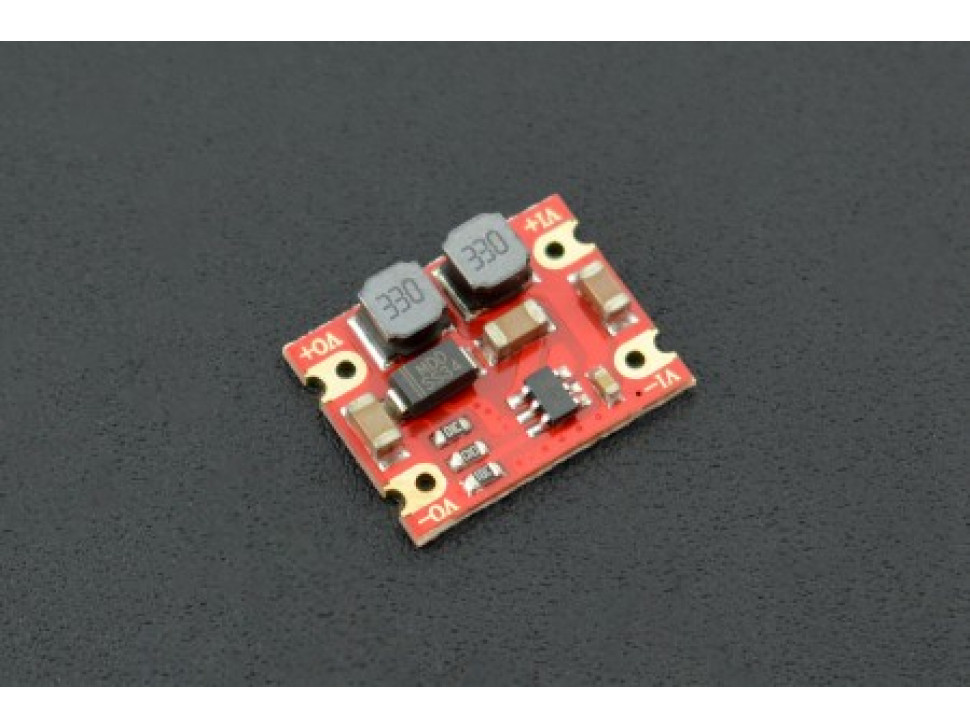
DC-DC Automatic Step Up-down Power Module 3~15V to 5V 600mA.
This module is capable of taking an input voltage of 3 to 15V and convert it to a stable 5V output voltage with a peak of 600mA current. Perfect for supplying an Adafruit Feather board and have sufficient current left to charge a battery. To use it, we attach a JST 2pin connector for the solar panel to the VI- and VI+ pads and a USB female connector to the VO- and VO+ pads.
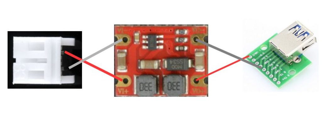
A straightforward diagram, and if you are sure about your projects, you can skip the connectors and connect the Solar panel directly to VI+ and VI- and your electronics board directly to VO+ and VO- with some wires.
The solar panel
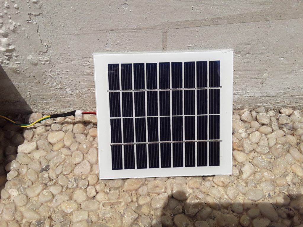
Looking into solar panels, you can find different capacities and different output voltages. For this project, I chose a panel with 9V voltage and 220mA current output, the Solar Panel 9V 220mA.
The reason to select this panel is the input range of the Step-up-down converter used. It accepts 3 to 15V input, so even if the panel is not in bright sunlight (and produces less voltage/current), it is sufficient to power your microcontroller. And the 9V panel has an output of max 11V without a load in bright sunshine, so we are below the maximum allowed input voltage.
In case you need more power (current) in your project, you can connect several Solar panels in parallel to the voltage converter to squeeze out more Amperes.
The selected Solar panel came without any wires attached, so the first thing to do is to use your multi-meter and find out which of the (initially unmarked) pins are Plus and Ground.
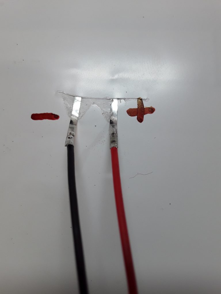
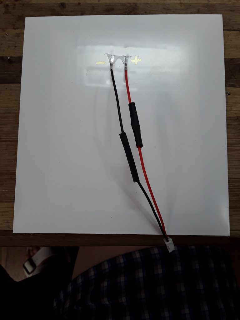
After we found out the polarization, we can solder a pair of wires (I used a wire set with a JST connector attached already, similar to this one JST-PH Battery Extension Cable 500mm).
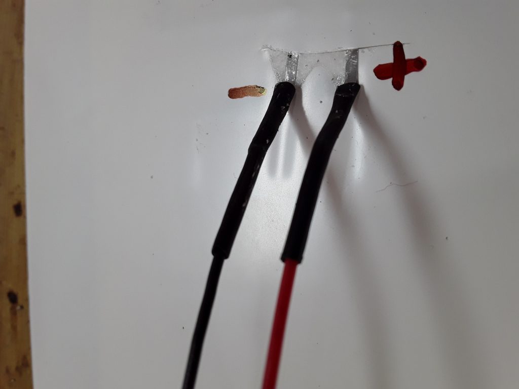
Shrink tube protects from accidentally contact.
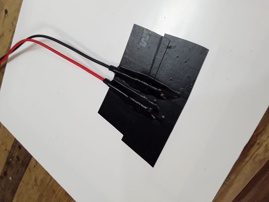
And finally, we cover the whole connection with some isolation tape.
For the final product, I am planning to create a 3D printed adjustable frame for the solar panel that
- protects the solder contacts
- protects the wire connectors from weather
- provides an adjustable mounting pole to place and fixate the panels securely.
And bringing all together
In my specific project, the task was to build up LoRa repeater to extend the (already broad) range of some LoRa equipped sensors to reach a LoRa gateway. (See my other projects LoRa Gateway and Battery powered LoRa sensor node).
In this specific case, the microcontroller used is not one of the Adafruit Feathers, but a custom board with an Insight ISP4520 module (Nordic nRF52 BLE chip + Semtech SX1262 LoRa chip in one module). The custom board already has a battery charging circuit on board, so the use of an external solar battery charger board would be a waste of money.
But of course, this tutorial can be used with any ESP32, ESP8266, or other Arduino boards that already have a battery charger circuit integrated.
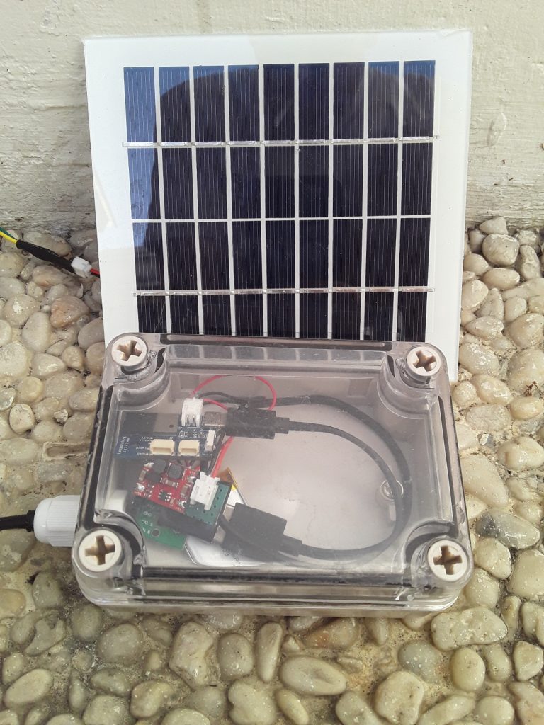
I used a weather-proofed enclosure to keep the battery, the step-up-down converter, and the electronics safe from rain and humidity (and insects;-p).
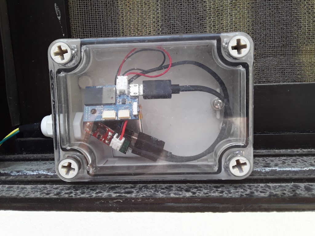
I really love these enclosures. They are a little bit expensive, but I had the opportunity to test them in a sugar cane field, covered with mud during a heavy rainfall without getting my electronics wet.
The wires leave the enclosure through a gland. It protects the system from water getting in (as long as you don’t submerge the thing into a lake).
And here the system in my backyard for testing:

It is now running for 3 days in a row. During the night, the battery capacity goes down to ~60%, but around 2-3 hours of direct sunlight onto the solar panels is enough to recharge the 500mAh LiPo battery to 100% before sunset.
Frequently Asked Questions
What does this Bring Solar Power Into Your Sensor Project tutorial cover?
Quite often, we want to place our sensors at locations where we have no access to a power outlet.
What's the working voltage of the Bring Solar Power Into Your Sensor Project?
Check the Sample Code section for the exact pinout — most maker-grade sensors run on 3.3V or 5V. Wire VCC to the matching rail, GND common with your MCU, data to a digital or analog pin.
Why does the Bring Solar Power Into Your Sensor Project read garbage or saturated values?
Three usual causes: wrong voltage rail, missing pull-up resistor on I2C lines (4.7k–10k to VCC), or a floating data pin. Double-check wiring against the diagram, then probe with a multimeter.