
Overview

When it is about radio communication, most think about the “famous” RFM95 and RFM96 modules. While these modules are well working and supported, they are based on an older technology from Semtech, the SX1272/SX1278 chips.
Since some time Semtech has a new generation of radio chips, the SX126x series. Compared with the SX127x series this new generation offers firstly lower battery consumption, secondly higher transmit power and thirdly better immunitiy to noise on the radio signal.
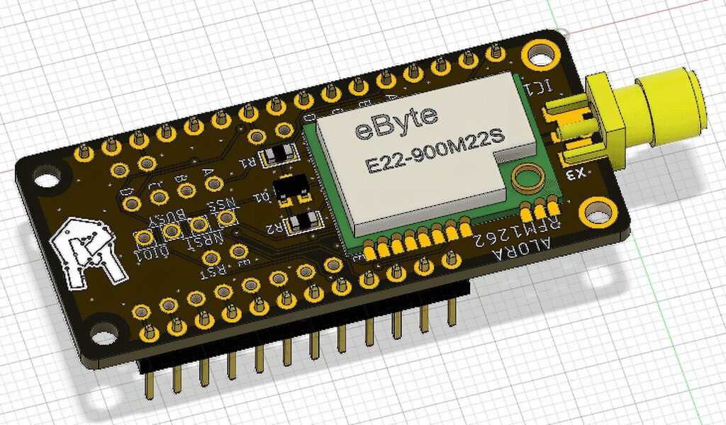
Because of these advantages the RFM1262 board utilizes the new Semtech SX1262 chip, moreover it has a continuous frequency coverage from 150MHz to 960MHz. Designed to be compatible with Adafruit Feathers, you can add long range communication features to your project.
Because the SX1262 offers a continous frequency coverage from 150MHz to 960MHz there is no need to buy different modules for different frequencies to be able to adapt the system to your regions regulations. One board does it all! All you have to do is to use an antenna that is matching the frequency you program to chip to send and receive.
Like the SX1272, the SX1262 uses SPI for interfacing, but the additional control lines are different. So if you want to switch from an RFM9x module to the RFM1262, you will have to adapt your software.
SX1262 Specs
- LoRa and FSK Modem
- 170 dB maximum link budget
- +22 dBm high efficiency PA
- Low RX current of 4.6 mA
- Integrated DC-DC converter and LDO
- Programmable bit rate up to 62.5 kbps LoRa and 300 kbps FSK
- High sensitivity: down to -148 dBm
- 88 dB blocking immunity at 1 MHz offset
- Co-channel rejection of 19 dB in LoRa mode
- FSK, GFSK, MSK, GMSK and LoRa modulation
- Built-in bit synchronizer for clock recovery
- Automatic Channel Activity Detection (CAD) with ultra-fast AFC
- Programmable RX/TX frequency from 150MHZ to 960MHz
Pinouts
SPI Data Pins (Fixed)
As all Feather boards have the SPI pins (MOSI/MISO/SCK) pins on the same pads, these signals are connected to these default pins
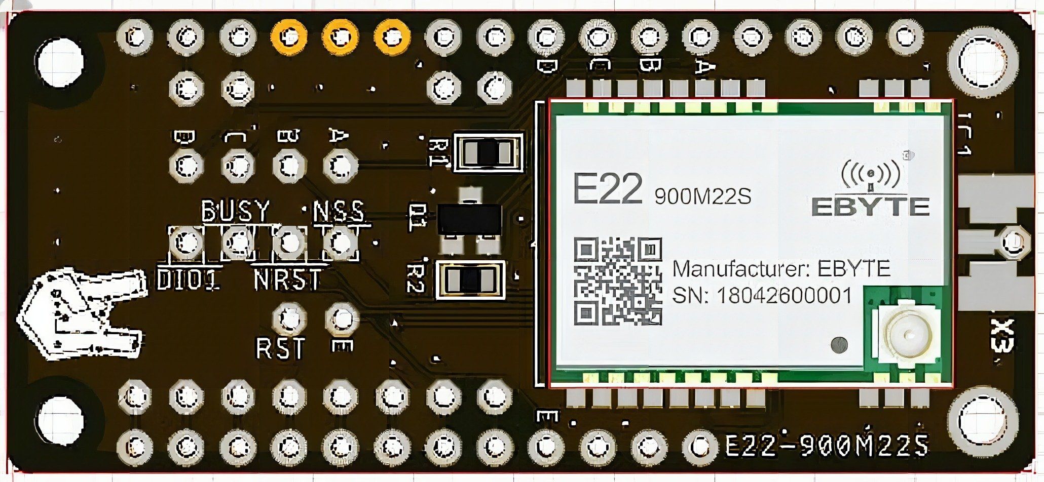
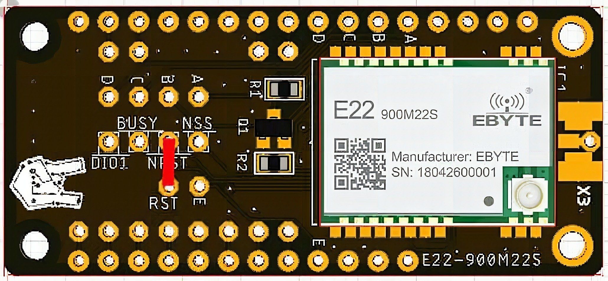
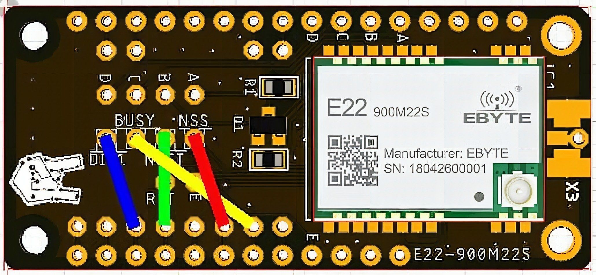
SX1262 Control Pins (Flexible)
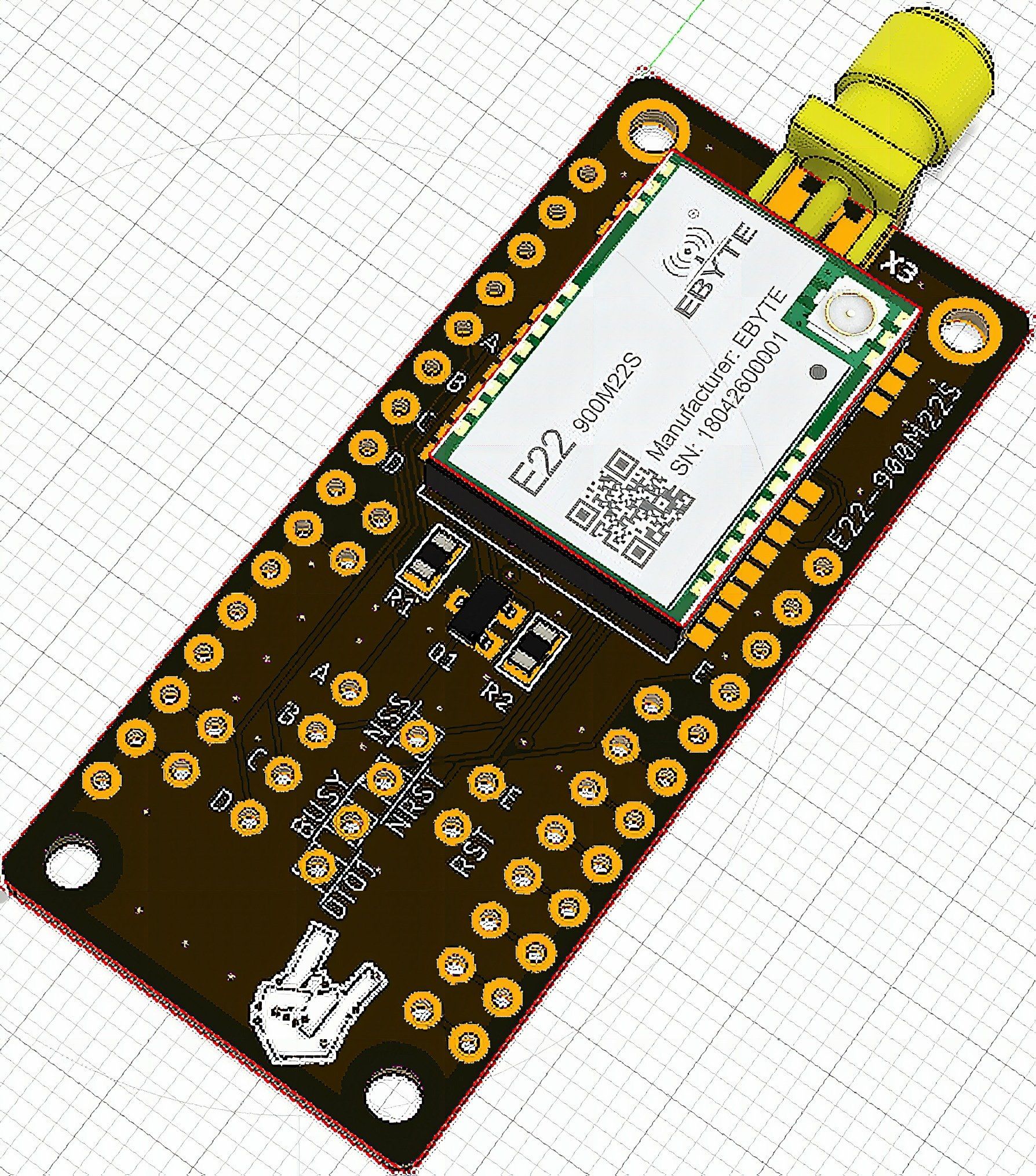
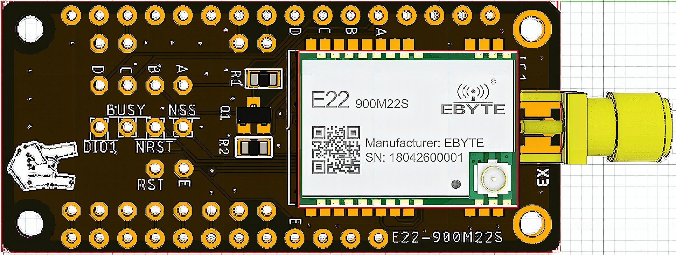
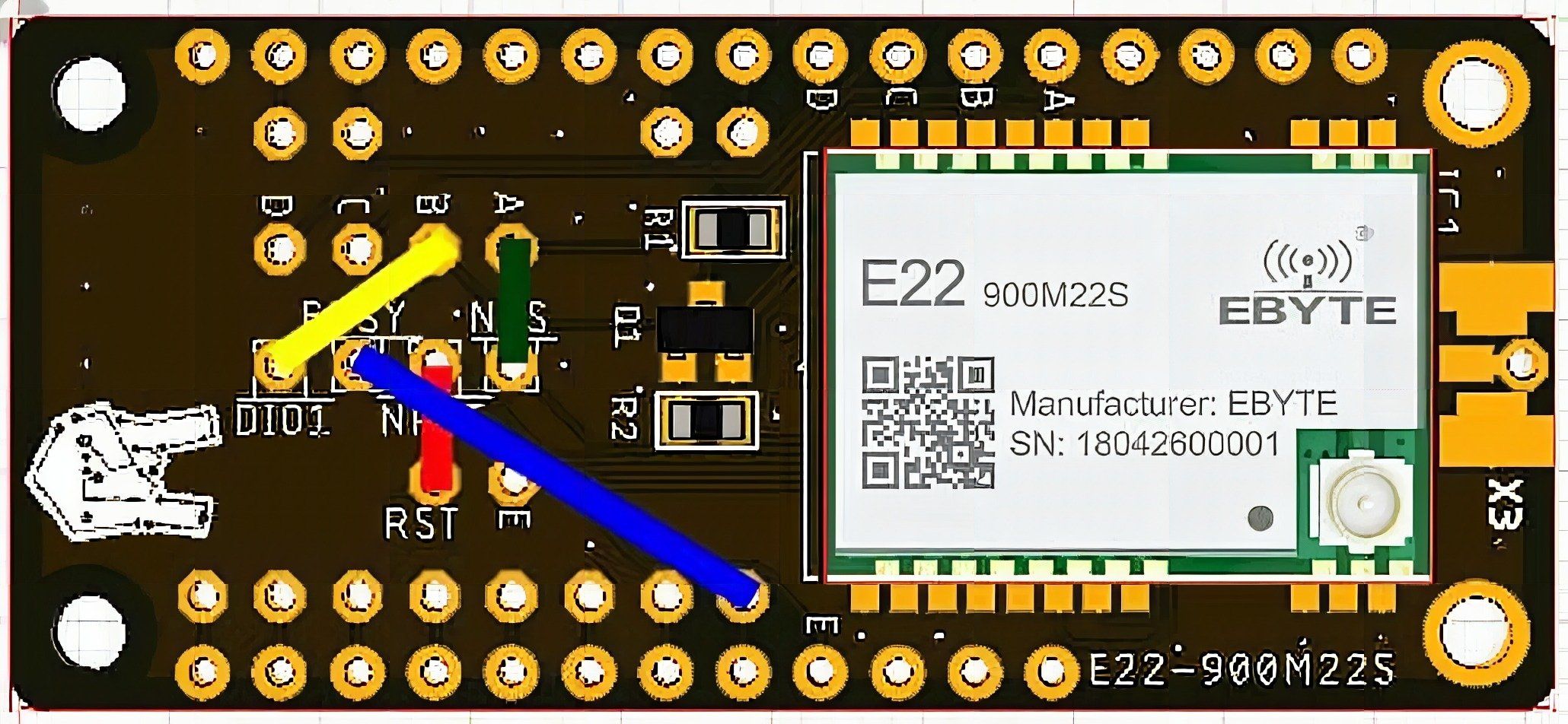
The SX1262 requires 4 pins to control the functions: NSS (CS), DIO1 (IRQ), BUSY and RST.
Because it is necessary to adapt the RFM1262 board to different base boards, these 4 signals can be connected to (nearly) any pin connected to the MCU board.
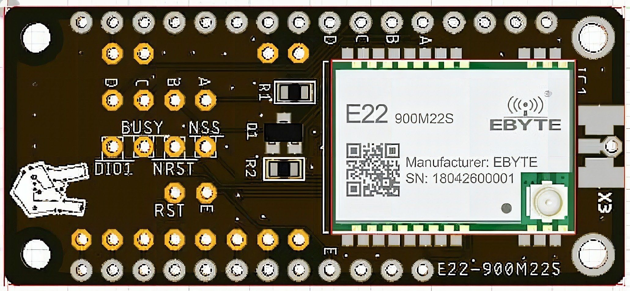
Wire these 4 signals with short jumpers like shown:
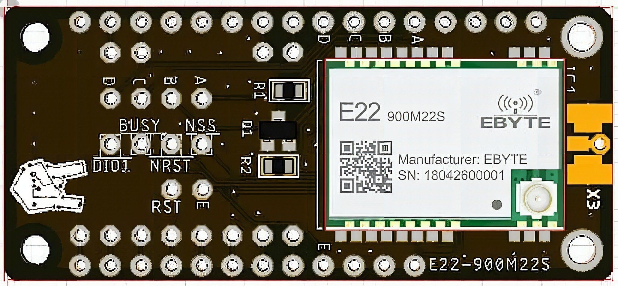
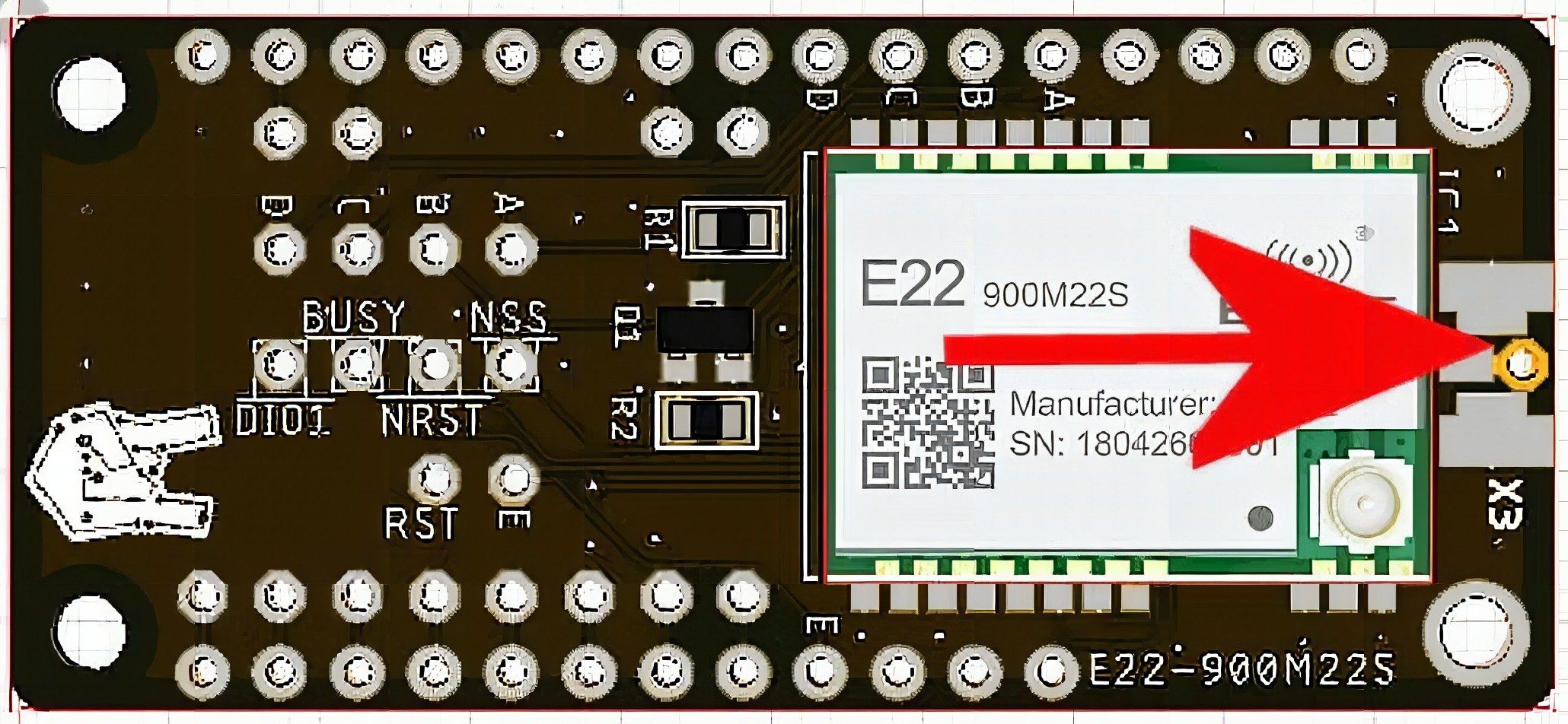
Antenna
There are 3 options to connect an antenna which we list here. In addition see the Assembly section to learn how to use them.
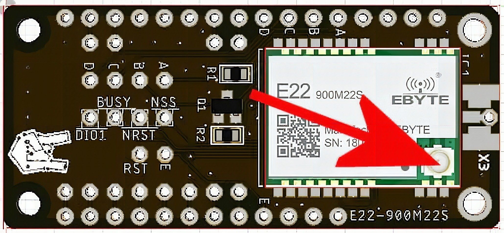
- – The U.FL connector on the LoRa module
- – A plain wire antenna soldered to the antenna pin
- – A SMA edge connector (not included) for use with any SMA connector
Wiring
If your project uses a Feather compatible processor board, the setup is easy. The only wiring required is to connect the 4 control pins to GPIOs of the processor board.
DIO1 (IRQ)
This is the most problematic signal, as you have to find out which pins of your processor board are interrupt capable.
BUSY
This signal is less critical, the only requirement is that the processor pin can be set as an input.
NSS(CS)
You can connect this signal to the default SPI CS pin of your processor board if you are using only one SPI device on the bus. However, if you are using more then one SPI device, the default SPI CS pin might be occupied already.
NRST(RST)
This signal is used to reset the SX1262 module (obviously). If you want to be able to reset the SX1262 module by software you need to connect this pin to any GPIO that can be set as an output.
On some processor boards the number of GPIOs are limited. Because of that you can connect NRST directly to the RST of your processor board. Conveniently, we placed a RST solder pad next to the NRST pad.
Courtesy of Adafruit Learn, they tested several Feather processor boards with the RFM95/RFM69 modules and moreover came up with some pin assignment proposals. We adapted these proposals to match the SX1262 requirements
ESP8266 Wiring
int PIN_LORA_NSS 0 // 5th pin on lowerside
int PIN_LORA_RESET 17 // Unused, connect to NRST on the board to RST int PIN_LORA_DIO_1 15 // IRQ pin 6th pin on lowerside
int PIN_LORA_BUSY 16 // 4th pin on lowerside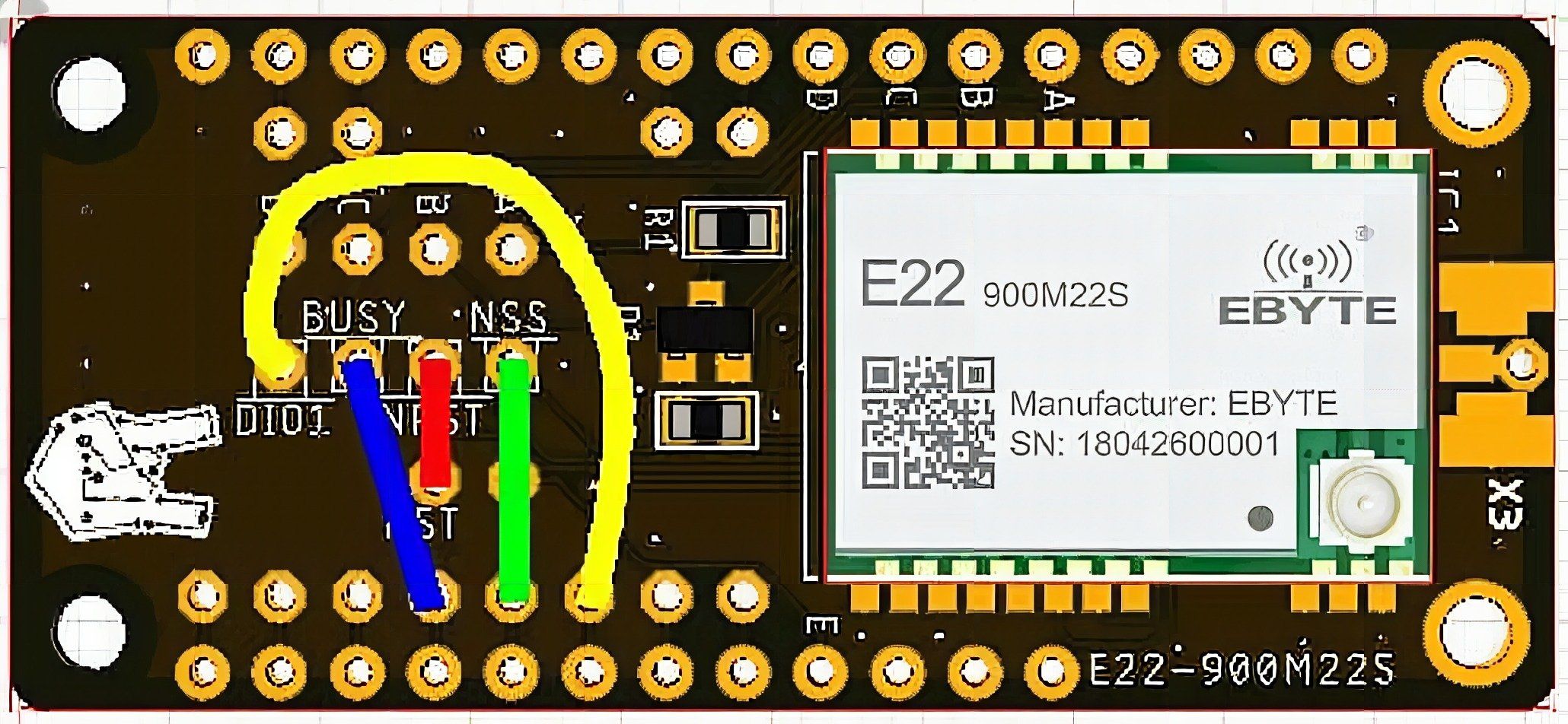
The ESP8266 is (as the 32u4) a difficult board. There are not many GPIO’s. If you want to have at least the I2C pins available to connect a sensor, the only possibility is to connect the RST of the SX1262 directly with the RST of the ESP8266.
Feather 32u4 Wiring
The 32u$ has only 4 IRQ pins which causes some conflict. This is because the only pins that can be used for IRQs are pins 0, 1, 2, and 3 which are as well the Serial RX/TX and I2C pins. So you have to give up on one of these interfaces
int PIN_LORA_NSS 5 // 3rd pin on lower side
int PIN_LORA_RESET 11 // 7th pin on lower side
int PIN_LORA_DIO_1 2 // 1st pin on lower side "SDA" (only SDA/SCL/RX/TX have IRQ!)
int PIN_LORA_BUSY 3 // 2nd pin on lower side "SCL" (We lost SDA already)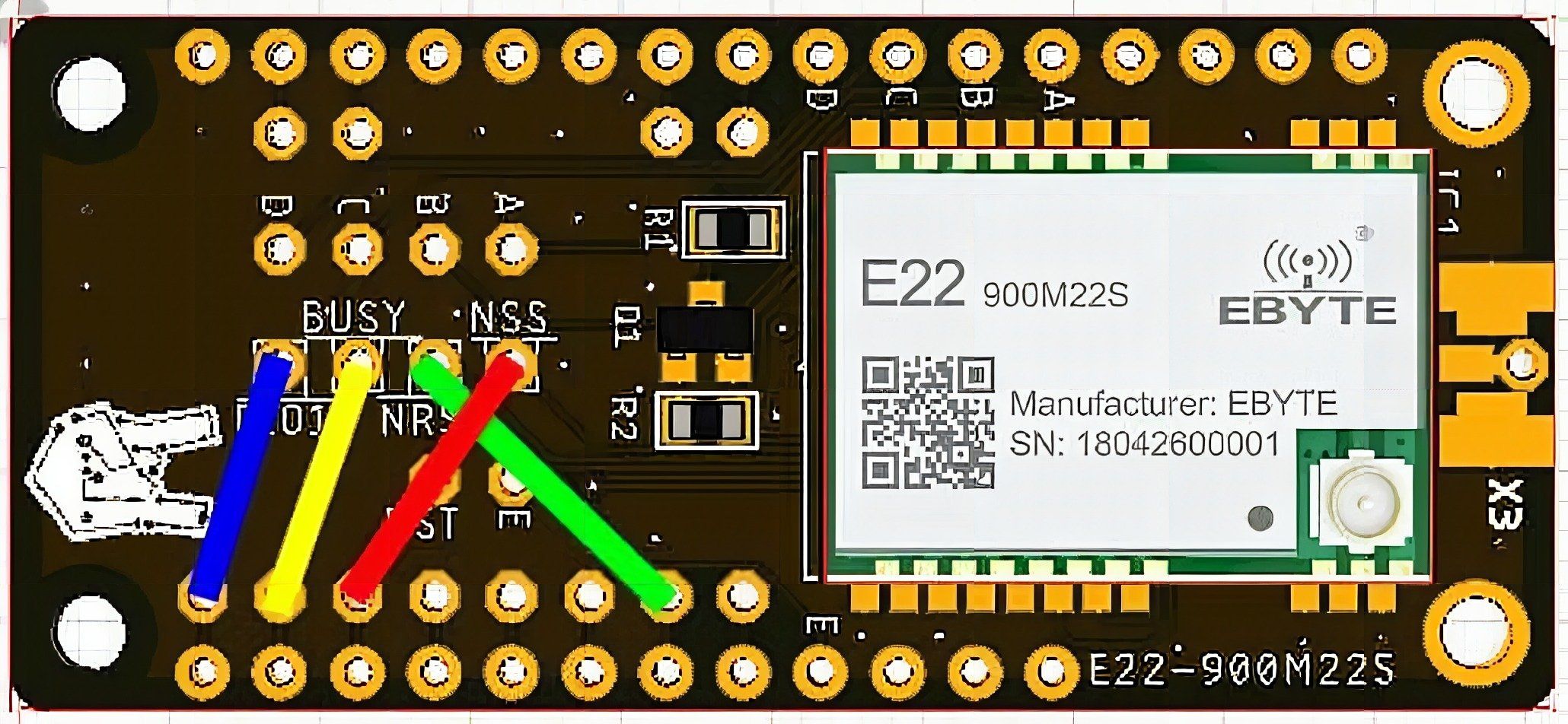
Feather M0, Feather M4, ESP32 Feather, nRF52xx Feather
Good that you are using one of these advanced boards. Because with these boards, you can basically use any of the GPIOs for the 4 signals.
Working example for the ESP32 Feather
int PIN_LORA_RESET = 32; // 4th pin on lower side
int PIN_LORA_DIO_1 = 14; // 3rd pin on lower side
int PIN_LORA_BUSY = 27; // 7th pin on lower side
int PIN_LORA_NSS = 33; // 6th pin on lower side
Assembly
Antenna Options
NEVER POWER UP THE MODULE WITHOUT AN ANTENNA CONNECTED. IT CAN DESTROY THE MODULE!
The system needs an antenna to send and receive. Therefor the module has three options for the connection, firstly an U.FL connector, secondly a simple solder pad for a wire antenna. And thirdly SMD pads to solder an SMA connector to the board.
Wire Antenna
The simplest and cheapest solution, but it might not give you the best performance. All you need is a piece of wire in the proper length for the frequency you want to use. Then you solder that wire into the ANT pad.
Courtesy of Adafruit, here are the lengths for the wire antenna for different frequencies:
433 MHz – 6.5 inches, or 16.5 cm
868 MHz – 3.25 inches or 8.2 cm
915 MHz – 3 inches or 7.8 cm
U.FL Connector
To ease the use of an antenna, the boards module has already an U.FL connector, so you can just plug in any antenna that comes with an U.FL connector.

SMA antenna
The most complicated way to connect an antenna. Because this requires you to solder a SMA connector to the board. As the pads are already there, all you need is to get your hands on a connector and solder it to the pins.
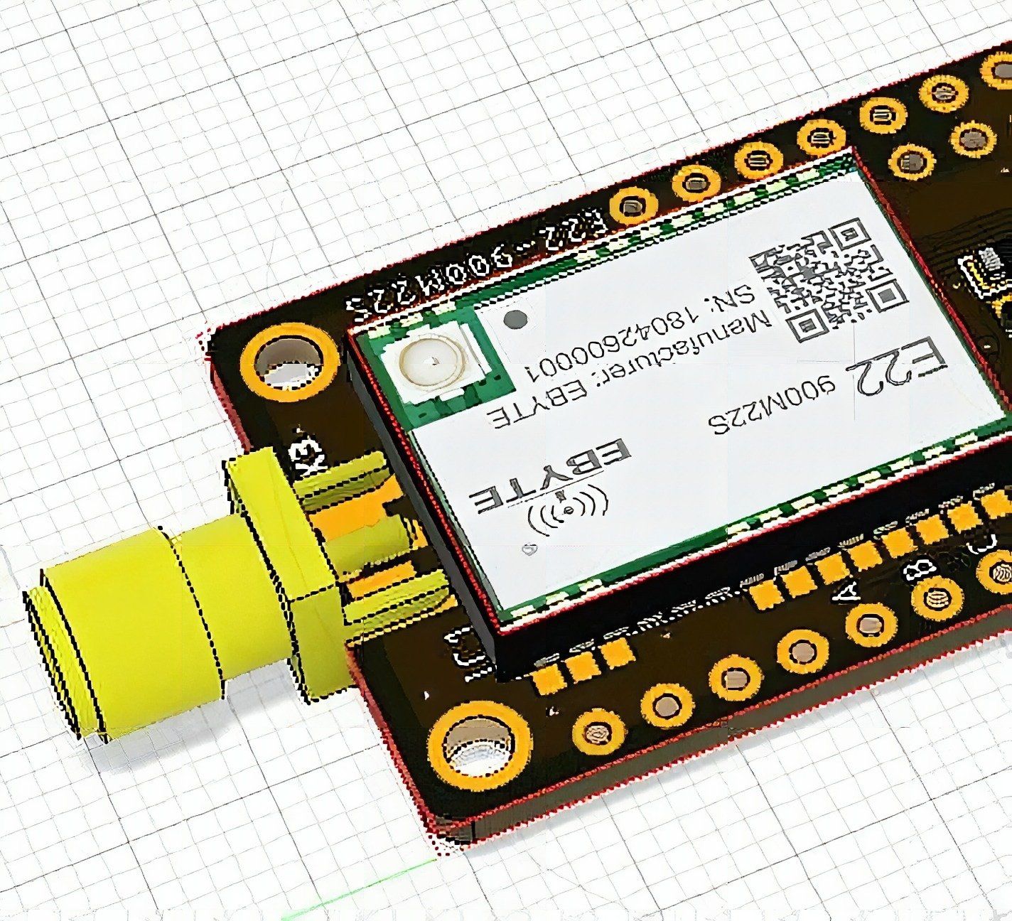
Antenna examples
For the U.FL and SMA connection there are several options. One often used type is the “whip” type, a plastic stick with the antenna inside. Because they are quite big you will have to decide if they fit into your project. Another type is an antenna made of flexible material. This type is often used in mobile devices. Because they are small, you can bend them to fit into your enclosure or just glue them to it.

Usage without a Feather board
If you want to use this board with other processor boards than a Feather board, e.g. on a breadboard, keep in mind:
This board is only 3.3V compatible. If you want to connect it e.g. to an Arduino UNO you have to use level shifters for all signals between the UNO and the board. The Arduino UNO’s SPI and GPIOs are all 5V logic level and it can destroy the board if you connect it directly to the UNO’s pins.
Using the RFM1262
How do you get the LoRa modules to work? To test LoRa you will need at least two boards with LoRa capability. The SX1262 can communicate with any other SX1262 (of course), but if programmed with the same parameters, it can as well communicate with an RFM95. But it cannot communicate with an RFM69! As a result, you can take one of your existing RFM95 modules and use it to communicate with an SX1262.
Program one of your boards with the PING sketch and the other board with the PONG sketch.
Be aware that the PingPong example is made for a communication between 2 LoRa nodes only. For a real life application with several sensor nodes sending data to a gateway node, see the link at the end of this post.
The Arduino library
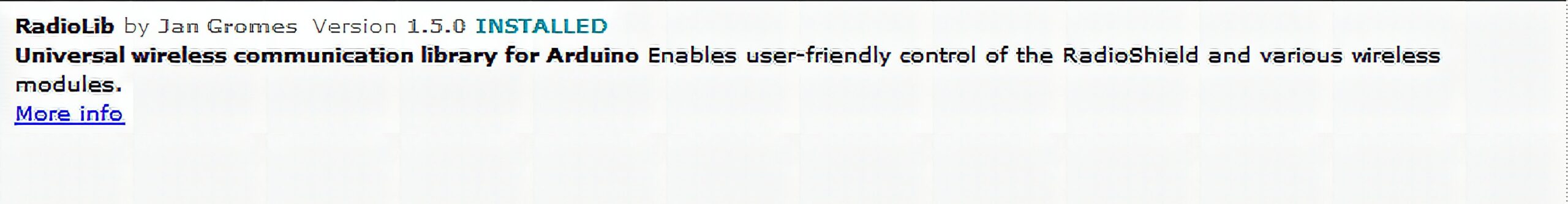
To use the radio module you need a library. At the time of writing there are 2 Arduino libraries available for the SX1262 chips. RadioLib from Jan Gromes is supporting a lot of different modules, not only LoRa but as well WiFi modules. I recommend this library if you just want to do simple LoRa communication. But if you want to connect your Alora SX1262 module to LoRaWan you should choose SX126x-Arduino. And yes, this library is written by myself. Beside of simple LoRa communication it supports as well the LoRaWan protocoll. But for now it is limited to ESP32, ESP8266 and Nordic nRF52 chips. AVR chips are not supported by the SX126x-Arduino library. If you want to learn more about what is LoRa and LoRaWan, I propose to read the article from i-scoop => LoRa and LoRaWAN
You might choose either library, it is up to your requirements (and programming skills). The examples below are using the RadioLib. You can easily install it with ArduinoIDE’s library manager.
PingPong example
We start with a simple example that sends and receives data, the PingPong code. It is often used to perform range tests for LoRa devices.
We will need 2 devices to run this example. The first device is named “node” which works as a master and initiates the communication. The second one is a “gateway” that starts listening and waiting for a message from the “node”. After it received a message, it will respond to the “node”.
Now why is it called PingPong? Very simple, because the data that the node sends is “PING” and the response from the gateway is “PONG”. So the two devices play PingPong;-)
There is as well a visual information about the connection status. The visual info is given with the onboard LED. If you want to make range tests, you will be most likely outdoors without the possibility to attach a computer to your modules to see the debug output. To see if the two devices under test can still communicate with each other, they light up their onboard LED to indicate a successful connection.
The “PING” sketch
Initialization
We are here to learn how to use LoRa modules. Therefor code is intentionally kept simple to make it easier to start.
First include the RadioLib library into your code. This is done by the line #include <RadioLib.h>
Pin definitions
As every Feather board has different processors and different GPIOs available, you need to define the connections of the LoRa modules NSS (SPI CS), DIO1 (IRQ), BUSY and RST to the processors GPIOs.
To make it simpler for the demo code, the code contains working pin combinations for the Feather 32u4, Feather Huzzah ESP8266, Feather Huzzah32 ESP32, Feather nRF52 Bluefruit LE, Feather nRF52840 Express, Feather 328P and Feather M0 boards. The correct connection for each board is automatically selected by compiler options.
#if defined(__AVR_ATmega32U4__)
/*********************************************************************/
/*********************************************************************/
/* Pin definitions for Adafruit Feather 32u4 Basic Proto */
/*********************************************************************/
/*********************************************************************/
// Change this to the GPIO connected to the RFM1262 NSS pin
#define RFM1262_NSS 5 // Default SPI CS
// Change this to the GPIO connected to the RFM1262 DIO1 pin
#define RFM1262_DIO1 0 // RxD
// Change this to the GPIO connected to the RFM1262 BUSY pin
#define RFM1262_BUSY 1 // TxD
// Change this to the GPIO connected to the RFM1262 RST pin
#define RFM1262_RST 11 // GPIO 11
#pragma message("Building for AVR 32U4!")
#elif defined (ESP8266)
/*********************************************************************/
/*********************************************************************/
/* Pin definitions for Adafruit Feather HUZZAH with ESP8266 */
/*********************************************************************/
/*********************************************************************/
// Change this to the GPIO connected to the RFM1262 NSS pin
#define RFM1262_NSS 0 // GPIO 2
// Change this to the GPIO connected to the RFM1262 DIO1 pin
#define RFM1262_DIO1 15 // GPIO 15
// Change this to the GPIO connected to the RFM1262 BUSY pin
#define RFM1262_BUSY 16 // GPIO 13
// Change this to the GPIO connected to the RFM1262 RST pin
#define RFM1262_RST 17 // unused to keep the I2C lines available
#pragma message("Building for ESP8266!")
#elif defined (ESP32)
/*********************************************************************/
/*********************************************************************/
/* Pin definitions for Adafruit HUZZAH32 ESP32 Feather board */
/*********************************************************************/
/*********************************************************************/
// Change this to the GPIO connected to the RFM1262 NSS pin
#define RFM1262_NSS 33 // GPIO 33
// Change this to the GPIO connected to the RFM1262 DIO1 pin
#define RFM1262_DIO1 14 // GPIO 6
// Change this to the GPIO connected to the RFM1262 BUSY pin
#define RFM1262_BUSY 27 // GPIO 9
// Change this to the GPIO connected to the RFM1262 RST pin
#define RFM1262_RST 32 // GPIO 13
#pragma message("Building for ESP32!")
#elif defined (__AVR_ATmega328P__)
/*********************************************************************/
/*********************************************************************/
/* Pin definitions for Adafruit Feather 328P */
/*********************************************************************/
/*********************************************************************/
// Change this to the GPIO connected to the RFM1262 NSS pin
#define RFM1262_NSS 5 // Default SPI CS
// Change this to the GPIO connected to the RFM1262 DIO1 pin
#define RFM1262_DIO1 2 // GPIO 2 - IRQ0
// Change this to the GPIO connected to the RFM1262 BUSY pin
#define RFM1262_BUSY 4 // GPIO 4
// Change this to the GPIO connected to the RFM1262 RST pin
#define RFM1262_RST 6 // GPIO 6
#pragma message("Building for AVR Mega 328!")
#elif defined (SAMD_SERIES)
/*********************************************************************/
/*********************************************************************/
/* Pin definitions for Adafruit Feather M0 */
/*********************************************************************/
/*********************************************************************/
// Change this to the GPIO connected to the RFM1262 NSS pin
#define RFM1262_NSS 5 // Default SPI CS
// Change this to the GPIO connected to the RFM1262 DIO1 pin
#define RFM1262_DIO1 6 // GPIO 6
// Change this to the GPIO connected to the RFM1262 BUSY pin
#define RFM1262_BUSY 9 // GPIO 9
// Change this to the GPIO connected to the RFM1262 RST pin
#define RFM1262_RST 13 // GPIO 13
#pragma message("Building for SAMD!")
#elif defined(NRF52832)
/*********************************************************************/
/*********************************************************************/
/* Pin definitions for Adafruit Feather nRF52 Bluefruit LE */
/*********************************************************************/
/*********************************************************************/
// Change this to the GPIO connected to the RFM1262 NSS pin
#define RFM1262_NSS 27 // GPIO 27
// Change this to the GPIO connected to the RFM1262 DIO1 pin
#define RFM1262_DIO1 30 // GPIO 30
// Change this to the GPIO connected to the RFM1262 BUSY pin
#define RFM1262_BUSY 31 // GPIO 31
// Change this to the GPIO connected to the RFM1262 RST pin
#define RFM1262_RST 11 // GPIO 11
#pragma message("Building for nRF52832!")
#elif defined(NRF52840)
/*********************************************************************/
/*********************************************************************/
/* Pin definitions for Adafruit Feather nRF52840 Express */
/*********************************************************************/
/*********************************************************************/
// Change this to the GPIO connected to the RFM1262 NSS pin
#define RFM1262_NSS 40 // GPIO 40 P1.08
// Change this to the GPIO connected to the RFM1262 DIO1 pin
#define RFM1262_DIO1 7 // GPIO 7 P0.07
// Change this to the GPIO connected to the RFM1262 BUSY pin
#define RFM1262_BUSY 26 // GPIO 26 P0.26
// Change this to the GPIO connected to the RFM1262 RST pin
#define RFM1262_RST 27 // GPIO 27 P0.27
#pragma message("Building for nRF52840!")
#else
#pragma message("Unsupported platform!")
#error Select supported platform.
#endif
Initialize the library
For most of the boards the initialization is simple as this
The RadioLib is intialized with parameters that define which GPIOs are used for NSS, DIO1, DIO2 and BUSY signals from the SX1262 module// NSS DIO1 DIO2 BUSY<br>SX1262 lora = new Module(RFM1262_NSS, RFM1262_DIO1, -1, RFM1262_BUSY);
The third parameter, DIO2 is set to – 1 because the module on the LoRa board does not use DIO2.
The ESP32 is an exception here (and other processors with more than one SPI interface
You have to tell the library which of the two SPI bus (HSPI or VSPI) should be used. On the Adafruit Huzzah32 Feather board the VSPI bus is connected to the Feathers SPI bus pinsSPIClass *loraSPI = new SPIClass(VSPI);// NSS DIO1 DIO2 BUSYSX1262 lora = new Module(RFM1262_NSS, RFM1262_DIO1, -1, RFM1262_BUSY, *loraSPI);
The setup()
In the setup function of your sketch the SX1262 chip is activated by calling the begin() function.// Initialize LoRa<br> // Paramters are frequency, bandwidth, coding rate, spreading factor<br> int state = lora.begin(868.0, 125.0, 8, 5);<br> if (state!= ERR_NONE)<br> {<br> Serial.printf("nLoRa begin failed %dnn", state);<br> }
The begin() function sets the LoRa parameters to be used, be aware that all modules that want to communicate to each other need to set to the same parameters!
Frequency
The LoRa is working in different reserved frequencies in different regions of the world. To find out what is the correct frequency for your location, a good source is this list provided by TheThingsNetwork.
For the Philippines the frequency would be between 863 and 870 MHz. You can choose any frequency in 125kHz steps. For more information look into All what you need to know about regulation on RF 868MHz for LPWan
Bandwidth, Coding Rate and Spreading factor
These parameters are influencing range and reliability of the LoRa communication. The defaults set here (125kHz bandwidth, spreading factor 8 and coding rate 4/5 are “standard”.
The article The Best LoRa Settings for Range and Reliability is a good starting point to learn more about how to optimize these parameters.
Controlling the antenna
The radio modules need to switch the antenna mode between transmitting and receiving because they use a single antenna. On the SX1262 this can be handled by the chip itself with the DIO2 output. But we have to tell the chip that this functionality is used by setting lora.setDio2AsRfSwitch(true);
Another feature of the SX1262 is that for power saving reasons another pin can be used to power-up/power-down the internal oscillator. On this module this feature is used as well, so again we have to tell the SX1262 about it by using lora.setTCXO(2.4);
Transmit power
When doing range tests, you want the best results. To achieve that you want to set your transmit power to maximum, to achieve this set the TX power with the command lora.setOutputPower(22);
And that’s all the setup needed. Now the module is ready to send or receive data. All of that is handled in the loop function.
The loop()
First we send a “PING” package you call lora.transmit((uint8_t *)pingMsg, sizeof(pingMsg)); with the data package and its length as parameter.
After sending we listen and wait for an incoming package you call lora.receive(dataMsg, sizeof(dataMsg))with a pointer to a receive buffer and the size of the receive buffer as parameters.
The receive() function will return one of the following results:
The code ERR_NONE means that a data package was received.
If no data was received the error ERR_RX_TIMEOUT is the result.
ERR_CRC_MISMATCH – meaning that data was received, but it was invalid
In case of ERR_NONE the received data package is analyzed and if it is a “PONG” message, then we send the next “PING” message.
If the result is ERR_RX_TIMEOUT we just restart to listen
In any other case we wait for 500ms and then send a “PING” message again.
The “PING” code:
>BERND, CODE TO BE VERIFIED WITH REAL MODULE<
#include <Arduino.h>
#include <RadioLib.h>
#include <Wire.h> #if defined(__AVR_ATmega32U4__)
/*********************************************************************/
/*********************************************************************/
/* Pin definitions for Adafruit Feather 32u4 Basic Proto */
/*********************************************************************/
/*********************************************************************/
// Change this to the GPIO connected to the RFM1262 NSS pin
#define RFM1262_NSS 5 // Default SPI CS
// Change this to the GPIO connected to the RFM1262 DIO1 pin
#define RFM1262_DIO1 0 // RxD
// Change this to the GPIO connected to the RFM1262 BUSY pin
#define RFM1262_BUSY 1 // TxD
// Change this to the GPIO connected to the RFM1262 RST pin
#define RFM1262_RST 11 // GPIO 11
#pragma message("Building for AVR 32U4!")
#elif defined (ESP8266)
/*********************************************************************/
/*********************************************************************/
/* Pin definitions for Adafruit Feather HUZZAH with ESP8266 */
/*********************************************************************/
/*********************************************************************/
// Change this to the GPIO connected to the RFM1262 NSS pin
#define RFM1262_NSS 2 // GPIO 2
// Change this to the GPIO connected to the RFM1262 DIO1 pin
#define RFM1262_DIO1 15 // GPIO 15
// Change this to the GPIO connected to the RFM1262 BUSY pin
#define RFM1262_BUSY 13 // GPIO 13
// Change this to the GPIO connected to the RFM1262 RST pin
#define RFM1262_RST 16 // GPIO 16
#pragma message("Building for ESP8266!")
#elif defined (ESP32)
/*********************************************************************/
/*********************************************************************/
/* Pin definitions for Adafruit HUZZAH32 ESP32 Feather board */
/*********************************************************************/
/*********************************************************************/
// Change this to the GPIO connected to the RFM1262 NSS pin
#define RFM1262_NSS 5 // Default SPI CS
// Change this to the GPIO connected to the RFM1262 DIO1 pin
#define RFM1262_DIO1 6 // GPIO 6
// Change this to the GPIO connected to the RFM1262 BUSY pin
#define RFM1262_BUSY 9 // GPIO 9
// Change this to the GPIO connected to the RFM1262 RST pin
#define RFM1262_RST 13 // GPIO 13
#pragma message("Building for ESP32!")
#elif defined (__AVR_ATmega328P__)
/*********************************************************************/
/*********************************************************************/
/* Pin definitions for Adafruit Feather 328P */
/*********************************************************************/
/*********************************************************************/
// Change this to the GPIO connected to the RFM1262 NSS pin
#define RFM1262_NSS 5 // Default SPI CS
// Change this to the GPIO connected to the RFM1262 DIO1 pin
#define RFM1262_DIO1 2 // GPIO 2 - IRQ0
// Change this to the GPIO connected to the RFM1262 BUSY pin
#define RFM1262_BUSY 4 // GPIO 4
// Change this to the GPIO connected to the RFM1262 RST pin
#define RFM1262_RST 6 // GPIO 6
#pragma message("Building for AVR Mega 328!")
#elif defined (SAMD_SERIES)
/*********************************************************************/
/*********************************************************************/
/* Pin definitions for Adafruit Feather M0 */
/*********************************************************************/
/*********************************************************************/
// Change this to the GPIO connected to the RFM1262 NSS pin
#define RFM1262_NSS 5 // Default SPI CS
// Change this to the GPIO connected to the RFM1262 DIO1 pin
#define RFM1262_DIO1 6 // GPIO 6
// Change this to the GPIO connected to the RFM1262 BUSY pin
#define RFM1262_BUSY 9 // GPIO 9
// Change this to the GPIO connected to the RFM1262 RST pin
#define RFM1262_RST 13 // GPIO 13
#pragma message("Building for SAMD!")
#elif defined(NRF52832)
/*********************************************************************/
/*********************************************************************/
/* Pin definitions for Adafruit Feather nRF52 Bluefruit LE */
/*********************************************************************/
/*********************************************************************/
// Change this to the GPIO connected to the RFM1262 NSS pin
#define RFM1262_NSS 27 // GPIO 27
// Change this to the GPIO connected to the RFM1262 DIO1 pin
#define RFM1262_DIO1 30 // GPIO 30
// Change this to the GPIO connected to the RFM1262 BUSY pin
#define RFM1262_BUSY 31 // GPIO 31
// Change this to the GPIO connected to the RFM1262 RST pin
#define RFM1262_RST 11 // GPIO 11
#pragma message("Building for nRF52832!")
#elif defined(NRF52840)
/*********************************************************************/
/*********************************************************************/
/* Pin definitions for Adafruit Feather nRF52840 Express */
/*********************************************************************/
/*********************************************************************/
// Change this to the GPIO connected to the RFM1262 NSS pin
#define RFM1262_NSS 40 // GPIO 40 P1.08
// Change this to the GPIO connected to the RFM1262 DIO1 pin
#define RFM1262_DIO1 7 // GPIO 7 P0.07
// Change this to the GPIO connected to the RFM1262 BUSY pin
#define RFM1262_BUSY 26 // GPIO 26 P0.26
// Change this to the GPIO connected to the RFM1262 RST pin
#define RFM1262_RST 27 // GPIO 27 P0.27
#pragma message("Building for nRF52840!")
#else
#pragma message("Unsupported platform!")
#error Select supported platform.
#endif #ifdef ESP32
// ESP32 SPI class
SPIClass *loraSPI = new SPIClass(VSPI);
// SX1262 class
// NSS DIO1 DIO2 BUSY
SX1262 lora = new Module(RFM1262_NSS, RFM1262_DIO1, -1, RFM1262_BUSY, *loraSPI);
#else
// SX1262 class
// NSS DIO1 DIO2 BUSY
SX1262 lora = new Module(RFM1262_NSS, RFM1262_DIO1, -1, RFM1262_BUSY);
#endif // The Ping message will be sent by the node
char pingMsg[] = "PING";
// The Pong message will be sent by the gateway
char pongMsg[] = "PONG";
// Tracks the time stamp of last packet received
long timeSinceLastPacket = 0; // For AVR chips
#define time_t unsigned long
#ifndef LED_BUILTIN
#define LED_BUILTIN 13
#endif void setup()
{ // Reset RFM1262 pinMode(RFM1262_RST, OUTPUT); digitalWrite(RFM1262_RST, LOW); delay(100); digitalWrite(RFM1262_RST, HIGH); delay(100); pinMode(LED_BUILTIN, OUTPUT); // Start serial communication Serial.begin(115200); Serial.println("====================================="); Serial.println("RFM1262 PingPong test - I AM PING"); Serial.println("====================================="); // Initialize LoRa int state = lora.begin(868.0, 125.0, 8, 5); if (state!= ERR_NONE) { Serial.println("nLoRa begin failed " + String(state)); } lora.setOutputPower(22); lora.setTCXO(2.4); lora.setDio2AsRfSwitch(true);
} void loop()
{ Serial.println("Sending a PING"); lora.transmit((uint8_t *)pingMsg, sizeof(pingMsg)); // We wait only 2 seconds for a reply from the gateway time_t waitForGateway = millis(); // Flag if a response was received bool gotReply = false; // Loop until we get a package or run into a timeout while (!gotReply) { // Check if data over LoRa is available int state = lora.receive((uint8_t *)pongMsg, sizeof(pongMsg)); switch (state) { case ERR_NONE: Serial.println("---"); digitalWrite(LED_BUILTIN, LOW); //Turn on status LED Serial.println("Got data package: " + String(pongMsg) + " RSSI: " + String(lora.getRSSI())); gotReply = true; break; case ERR_RX_TIMEOUT: // Serial.println("Receive timeout"); break; case ERR_CRC_MISMATCH: Serial.println("CRC mismatch"); break; default: Serial.println("Unknown error " + String(state)); break; } if ((millis() - waitForGateway) > 2000) { // Timeout ==> Finish the waiting loop Serial.println("Timeout after " + String(millis() - waitForGateway)); break; } } if (!gotReply) { // Didn't get response for 2 seconds digitalWrite(LED_BUILTIN, HIGH); //Turn off status LED Serial.println("Receive failed, is the PONG running?"); // We will send the next PING immediately! } else { // We received a PONG, send the next PING after 500ms delay(500); }
}
The “PONG” code
The Pong code is very similar to the “node” code. The initialization and setup is identical. The difference is in the loop.
Instead of immediately sending a “PING” the code waits for a “PING” message and then replies with a “PONG”.
> BERND, CODE TO BE VERIFIED WITH REAL MODULE<
#include <Arduino.h>
#include <RadioLib.h>
#include <Wire.h> #if defined(__AVR_ATmega32U4__)
/*********************************************************************/
/*********************************************************************/
/* Pin definitions for Adafruit Feather 32u4 Basic Proto */
/*********************************************************************/
/*********************************************************************/
// Change this to the GPIO connected to the RFM1262 NSS pin
#define RFM1262_NSS 5 // Default SPI CS
// Change this to the GPIO connected to the RFM1262 DIO1 pin
#define RFM1262_DIO1 0 // RxD
// Change this to the GPIO connected to the RFM1262 BUSY pin
#define RFM1262_BUSY 1 // TxD
// Change this to the GPIO connected to the RFM1262 RST pin
#define RFM1262_RST 11 // GPIO 11
#pragma message("Building for AVR 32U4!")
#elif defined (ESP8266)
/*********************************************************************/
/*********************************************************************/
/* Pin definitions for Adafruit Feather HUZZAH with ESP8266 */
/*********************************************************************/
/*********************************************************************/
// Change this to the GPIO connected to the RFM1262 NSS pin
#define RFM1262_NSS 2 // GPIO 2
// Change this to the GPIO connected to the RFM1262 DIO1 pin
#define RFM1262_DIO1 15 // GPIO 15
// Change this to the GPIO connected to the RFM1262 BUSY pin
#define RFM1262_BUSY 13 // GPIO 13
// Change this to the GPIO connected to the RFM1262 RST pin
#define RFM1262_RST 16 // GPIO 16
#pragma message("Building for ESP8266!")
#elif defined (ESP32)
/*********************************************************************/
/*********************************************************************/
/* Pin definitions for Adafruit HUZZAH32 ESP32 Feather board */
/*********************************************************************/
/*********************************************************************/
// Change this to the GPIO connected to the RFM1262 NSS pin
#define RFM1262_NSS 5 // Default SPI CS
// Change this to the GPIO connected to the RFM1262 DIO1 pin
#define RFM1262_DIO1 6 // GPIO 6
// Change this to the GPIO connected to the RFM1262 BUSY pin
#define RFM1262_BUSY 9 // GPIO 9
// Change this to the GPIO connected to the RFM1262 RST pin
#define RFM1262_RST 13 // GPIO 13
#pragma message("Building for ESP32!")
#elif defined (__AVR_ATmega328P__)
/*********************************************************************/
/*********************************************************************/
/* Pin definitions for Adafruit Feather 328P */
/*********************************************************************/
/*********************************************************************/
// Change this to the GPIO connected to the RFM1262 NSS pin
#define RFM1262_NSS 5 // Default SPI CS
// Change this to the GPIO connected to the RFM1262 DIO1 pin
#define RFM1262_DIO1 2 // GPIO 2 - IRQ0
// Change this to the GPIO connected to the RFM1262 BUSY pin
#define RFM1262_BUSY 4 // GPIO 4
// Change this to the GPIO connected to the RFM1262 RST pin
#define RFM1262_RST 6 // GPIO 6
#pragma message("Building for AVR Mega 328!")
#elif defined (SAMD_SERIES)
/*********************************************************************/
/*********************************************************************/
/* Pin definitions for Adafruit Feather M0 */
/*********************************************************************/
/*********************************************************************/
// Change this to the GPIO connected to the RFM1262 NSS pin
#define RFM1262_NSS 5 // Default SPI CS
// Change this to the GPIO connected to the RFM1262 DIO1 pin
#define RFM1262_DIO1 6 // GPIO 6
// Change this to the GPIO connected to the RFM1262 BUSY pin
#define RFM1262_BUSY 9 // GPIO 9
// Change this to the GPIO connected to the RFM1262 RST pin
#define RFM1262_RST 13 // GPIO 13
#pragma message("Building for SAMD!")
#elif defined(NRF52832)
/*********************************************************************/
/*********************************************************************/
/* Pin definitions for Adafruit Feather nRF52 Bluefruit LE nRF52832 */
/*********************************************************************/
/*********************************************************************/
// Change this to the GPIO connected to the RFM1262 NSS pin
#define RFM1262_NSS 27 // GPIO 27
// Change this to the GPIO connected to the RFM1262 DIO1 pin
#define RFM1262_DIO1 30 // GPIO 30
// Change this to the GPIO connected to the RFM1262 BUSY pin
#define RFM1262_BUSY 31 // GPIO 31
// Change this to the GPIO connected to the RFM1262 RST pin
#define RFM1262_RST 11 // GPIO 11
#pragma message("Building for nRF52832!")
#elif defined(NRF52840)
/*********************************************************************/
/*********************************************************************/
/* Pin definitions for Adafruit Feather nRF52840 Express */
/*********************************************************************/
/*********************************************************************/
// Change this to the GPIO connected to the RFM1262 NSS pin
#define RFM1262_NSS 40 // GPIO 40 P1.08
// Change this to the GPIO connected to the RFM1262 DIO1 pin
#define RFM1262_DIO1 7 // GPIO 7 P0.07
// Change this to the GPIO connected to the RFM1262 BUSY pin
#define RFM1262_BUSY 26 // GPIO 26 P0.26
// Change this to the GPIO connected to the RFM1262 RST pin
#define RFM1262_RST 27 // GPIO 27 P0.27
#pragma message("Building for nRF52840!")
#else
#pragma message("Unsupported platform!")
#error Select supported platform.
#endif #ifdef ESP32
// ESP32 SPI class
SPIClass *loraSPI = new SPIClass(VSPI);
// SX1262 class
// NSS DIO1 DIO2 BUSY
SX1262 lora = new Module(RFM1262_NSS, RFM1262_DIO1, -1, RFM1262_BUSY, *loraSPI);
#else
// SX1262 class
// NSS DIO1 DIO2 BUSY
SX1262 lora = new Module(RFM1262_NSS, RFM1262_DIO1, -1, RFM1262_BUSY);
#endif // The Ping message will be sent by the node
char pingMsg[] = "PING";
// The Pong message will be sent by the gateway
char pongMsg[] = "PONG";
// Tracks the time stamp of last packet received
long timeSinceLastPacket = 0; // For AVR chips
#define time_t unsigned long
#ifndef LED_BUILTIN
#define LED_BUILTIN 13
#endif void setup()
{ // Reset RFM1262 pinMode(RFM1262_RST, OUTPUT); digitalWrite(RFM1262_RST, LOW); delay(100); digitalWrite(RFM1262_RST, HIGH); delay(100); pinMode(LED_BUILTIN, OUTPUT); // Start serial communication Serial.begin(115200); Serial.println("====================================="); Serial.println("RFM1262 PingPong test - I AM PONG"); Serial.println("====================================="); // Initialize LoRa int state = lora.begin(868.0, 125.0, 8, 5); if (state!= ERR_NONE) { Serial.println("nLoRa begin failed " + String(state)); } lora.setOutputPower(22); lora.setTCXO(2.4); lora.setDio2AsRfSwitch(true);
} void loop()
{ // We wait only 2 seconds for a reply from the gateway time_t waitForGateway = millis(); // Flag if a response was received bool gotReply = false; // Loop until we get a package or run into a timeout while (!gotReply) { // Check if data over LoRa is available int state = lora.receive((uint8_t *)pongMsg, sizeof(pongMsg)); switch (state) { case ERR_NONE: Serial.println("---"); digitalWrite(LED_BUILTIN, LOW); //Turn on status LED Serial.println("Got data package: " + String(pongMsg) + " RSSI: " + String(lora.getRSSI())); gotReply = true; Serial.println("Sending a PONG"); lora.transmit((uint8_t *)pongMsg, sizeof(pongMsg)); break; case ERR_RX_TIMEOUT: // Serial.println("Receive timeout"); break; case ERR_CRC_MISMATCH: Serial.println("CRC mismatch"); break; default: Serial.println("Unknown error " + String(state)); break; } if ((millis() - waitForGateway) > 2000) { // Timeout ==> Finish the waiting loop Serial.println("Timeout after " + String(millis() - waitForGateway)); break; } } if (!gotReply) { // Didn't get response for 2 seconds digitalWrite(LED_BUILTIN, HIGH); //Turn off status LED Serial.println("Receive failed, is the PING running?"); }
}
What’s next?
Now you want to know how to go on? Of course, the above code is just for a basic test and introduction how to use LoRa. To go deeper into the LoRa world, we have another learn blog here that shows how to setup a LoRa sensor node and a gateway to send the data to the IoT cloud. First go to Battery powered LoRa sensor node to learn how to program a sensor node and second go to LoRa Gateway to find out how you can send your sensor data to the IoT cloud.
If you want to go further, there are more examples in our Github repository for this board.
Downloads
Datasheets and Files
- SX1261-SX1262 Product Datasheet – The SX1262 LoRa radio chip
- E22-900M22S – The module used on the board
- Eagle CAD schematics and PCB
- 3D files
- Software examples
Schematic

Fabrication Prints

Frequently Asked Questions
[faq] [faq_q]What is the difference between RFM1262 and RFM95/96?[/faq_q] [faq_a]The RFM1262 uses the SX1262 chip, the newer LoRa SX126x family, with better sensitivity and lower power than the RFM95/96 (SX127x). Both use LoRa modulation but have different SPI register layouts, so libraries are not directly interchangeable.[/faq_a][faq_q]What is the maximum range of the RFM1262 in real-world conditions?[/faq_q] [faq_a]Line-of-sight tests have hit 10+ km at SF12 with the lowest bandwidth. Urban or treed environments typically deliver 1-3 km. The Alora variant ships with an SMA antenna connector so external high-gain antennas extend the range further.[/faq_a][faq_q]Does the RFM1262 work with LoRaWAN?[/faq_q] [faq_a]Yes. The SX1262 chip inside supports LoRaWAN class A, B, and C. You will need a LoRaWAN library like LMIC or RadioLib and a LoRaWAN gateway in range.[/faq_a][faq_q]What microcontroller works best with the Alora RFM1262?[/faq_q] [faq_a]ESP32 and STM32 are common choices because of their SPI speed and ample memory. Arduino Uno works for basic point-to-point but is tight on RAM if you use full LoRaWAN.[/faq_a][faq_q]Is the RFM1262 the same as the SX1262?[/faq_q] [faq_a]The SX1262 is the LoRa transceiver chip from Semtech. The RFM1262 is a module from HopeRF that wraps the SX1262 with passives and a matching network on a small breakout PCB.[/faq_a][/faq]Frequently Asked Questions
What does this Alora RFM1262 tutorial cover?
Overview When it is about radio communication, most think about the “famous” RFM95 and RFM96 modules.
What's the working voltage of the Alora RFM1262?
Check the Sample Code section for the exact pinout — most maker-grade sensors run on 3.3V or 5V. Wire VCC to the matching rail, GND common with your MCU, data to a digital or analog pin.
Why does the Alora RFM1262 read garbage or saturated values?
Three usual causes: wrong voltage rail, missing pull-up resistor on I2C lines (4.7k–10k to VCC), or a floating data pin. Double-check wiring against the diagram, then probe with a multimeter.