
Want to make a quick prototype with some sensors and your Feather boards? Then you might stumble over the same problem we did. The Feather system is great as long as you only need to put some Feathers and some Wings together. But how do you connect your sensors, actuators or display? Well, you can buy a FeatherWing proto board, solder connectors and wires to it and plug your sensors, actuators or display in. But wait, what if your sensor is one of the Sparkfun sensors with a QWIIC connector? Good luck with soldering the 1mm pitch QWIIC connector to a prototype board.
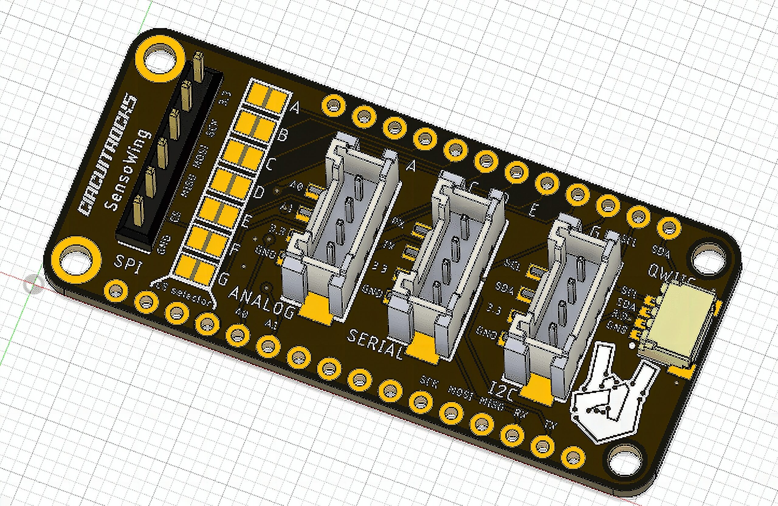
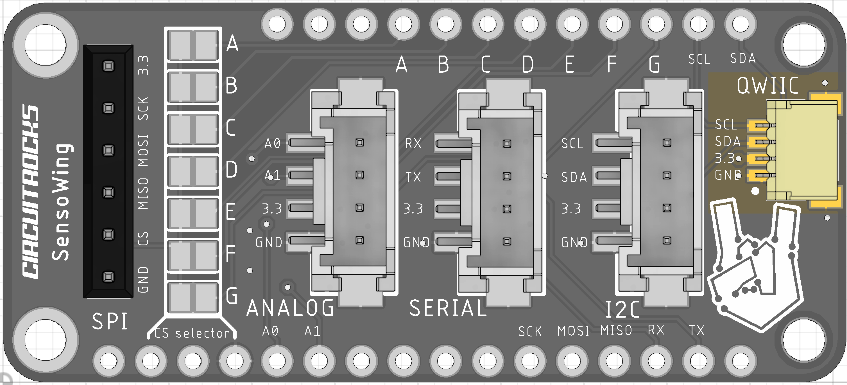
Don’t worry anymore, all these struggles made us think that a Feather with connectors is a good idea. Our SensoWing has 5 connectors, already wired to the standard I2C, SPI, Serial and Analog ports of the Feathers. SensoWing carries
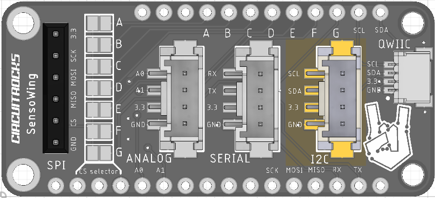
QWIIC I2C
The cables for QWIIC connectors are color coded. Double check that
- black wire connects to the GND pin
- red wire connects to the 3.3 pin
- blue wire connects to the SDA pin
- yellow wire connects to the SCL pin
The SDA and SCL pins are connected to the default I2C pins of the Feather.
Grove I2C
Same as QWIIC connectors, Grove cables are color coded. Keep in mind that Feathers are based on 3.3V supply. So if you plug in a Grove twig (module) that requires 5V supply it will not work.
- black wire connects to GND pin
- red wire connects to 3.3 pin
- white wire connects to SDA pin
- yellow wire connects to SCL pin
The SDA and SCL pins are connected to the default I2C pins of the Feather.
You can plug in I2C modules in both QWIIC and Grove I2C at the same time. Just make sure that only one module has pull-up resistors.
Grove Serial
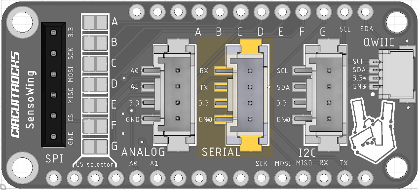
The RX and TX lines of the Grove Serial connector are wired to the default Serial pins of the Feather.
- black wire connects to GND pin
- red wire connects to 3.3 pin
- white wire connects to TX pin
- yellow wire connects to RX pin
Remember that some Feathers have only one serial port, e.g. the ESP8266 Huzzah Feather. So when you use one of these Feathers, the Serial connector cannot be used. But check at the end of this article to find some solutions.
Grove Analog
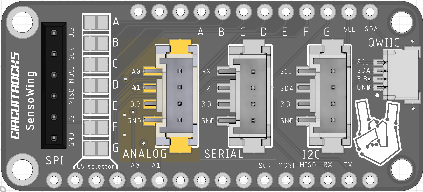
The Grove Analog connector is wired to the A0 and A1 pins of the Feather system. Depending on the Feather you are using only one analog input (A0) might be available. E.g. the ESP8266 Huzzah Feather has only one AD converter.
On some Feathers the A0 and A1 pins can be as well an analog output, e.g. the ESP32 Huzzah Feather has 2 DA channels which can are shared with 2 AD channels. You can program A0 and/or A1 as analog output or analog input.
Make sure the analog voltage you connect here matches with the maximum supported voltage of your Feather. E.g. the ESP8266 AD input supports only 1.1V!
- black wire connects to GND pin
- red wire connects to 3.3 pin
- white wire connects to A1 pin
- yellow wire connects to A0 pin
SPI header
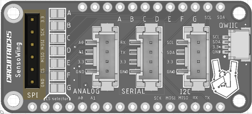
For SPI there is no standardized connector defined. So we added just a header where you can plug in your SPI module.
As different Feather have different GPIOs as their default SPI chip select output, we added a bunch of solder bridges that allows you connect the CS signal to any of 7 GPIOs. Just make sure you have only one of the bridges closed!

You need something different?
Well, not everybody is happy with the selection of the connectors we did. But on modern CPU’s like the ESP32 you can assign nearly every GPIO to I2S, SPI, I2S,…..
So you are not stuck with the names on the SensoWing board. You can plug in and use the connectors for whatever you want.
The SensoWing comes without headers soldered to it, so you can solder your own choice of headers to it.
Applications:
Quick prototyping.
Specifications:
- 1 x 1mm pitch I2C connector compatible with Sparkfuns QWIIC standard.
- 1 x I2C connector compatible with Seeed Studio Grove standard.
- 1 x Serial connecter compatible with Seeed Studio Grove standard.
- 1 x Analog in or out connector compatible with Seeed Studio Grove standard.
- 1 x header with SPI bus
- SPI chip select connected to any available GPIO by putting a simple solder bridge
Technical details:
EagleCAD PCB files, datasheets and more on Github
Dimensions 2.0”x0.9”x0.28” (51mmx23mmx8mm)
Frequently Asked Questions
What does this Circuitrocks SensoWing tutorial cover?
Want to make a quick prototype with some sensors and your Feather boards? Then you might stumble over the same problem we did.
What's the working voltage of the Circuitrocks SensoWing?
Check the Sample Code section for the exact pinout — most maker-grade sensors run on 3.3V or 5V. Wire VCC to the matching rail, GND common with your MCU, data to a digital or analog pin.
Why does the Circuitrocks SensoWing read garbage or saturated values?
Three usual causes: wrong voltage rail, missing pull-up resistor on I2C lines (4.7k–10k to VCC), or a floating data pin. Double-check wiring against the diagram, then probe with a multimeter.