
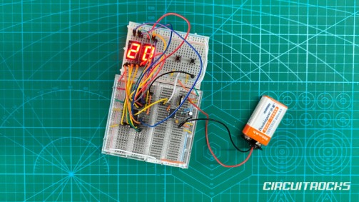
Want to build a counter that works without Arduino programming? ⚙️⚡️This 2 Digit Digital Counter uses electronic ICs to count from 00 to 99 and show the result on two 7-segment displays. Instead of uploading code, the circuit uses an NE555 timer IC to create pulses and two CD4026 ICs to count and display the numbers.
This project is a good introduction to hardware-based digital counting. The first 7-segment display shows the ones digit, while the second display shows the tens digit. Each pulse moves the counter forward, and the display changes based on the count. Because the result appears directly on the displays, the project is easy to test and easy to demonstrate.
The build also includes a stable power section using a 9V battery and an LM7805 voltage regulator. The LM7805 provides a regulated 5V supply for the ICs and displays. The capacitors help smooth the voltage so the circuit can run more reliably. With the reset and next buttons, the project becomes a complete two-digit counter circuit that users can control manually.
Why Build?
This project is worth building because it helps you understand how digital counters work without relying on software. Many beginner projects use Arduino code to count and display numbers, but this circuit shows the same idea using hardware logic. The NE555 generates the pulse, the CD4026 counts it, and the 7-segment displays show the result. This makes the project useful for learning basic electronics at the circuit level.
It also teaches how a 7-segment display forms numbers. Each display has LED segments that turn on in different combinations to show digits from 0 to 9. The CD4026 makes this easier because it already includes counter and display-driver functions. Because of that, you do not need to control each segment manually using many separate gates.
The power section is another important part of the build. A 9V battery alone is too high for the IC logic, so the LM7805 brings it down to a safer and more stable 5V. The 0.1µF ceramic capacitor and 10µF capacitor help reduce noise and voltage changes. This gives the counter a more stable supply, which helps prevent random counting or display glitches.
This project also has strong demo value. Pressing the next button can move the count forward, while the reset button can return the display to zero. Viewers can immediately see what the circuit does because the output appears on the two 7-segment displays. That makes it useful for school projects, electronics lessons, and beginner digital logic demonstrations.
What You’ll Learn
By building this 2 Digit Digital Counter, you’ll learn:
- How a hardware counter can count without Arduino code.How an NE555 timer IC can create clock pulses.
- How a CD4026 IC counts pulses and drives a 7-segment display.
- How two CD4026 ICs can work together for ones and tens digits.
- How a 7-segment display shows numbers using LED segments.
- How a reset button clears the count back to zero.How a next button can send or trigger a count pulse.
- How an LM7805 voltage regulator converts 9V into 5V.Why capacitors help stabilize the power supply.
- How resistors help protect LED segments and circuit inputs.
- How breadboard wiring can connect ICs, buttons, displays, and power rails.
- How this circuit can become a tally counter, scoreboard, timer display, or object counter.
What You’ll Need
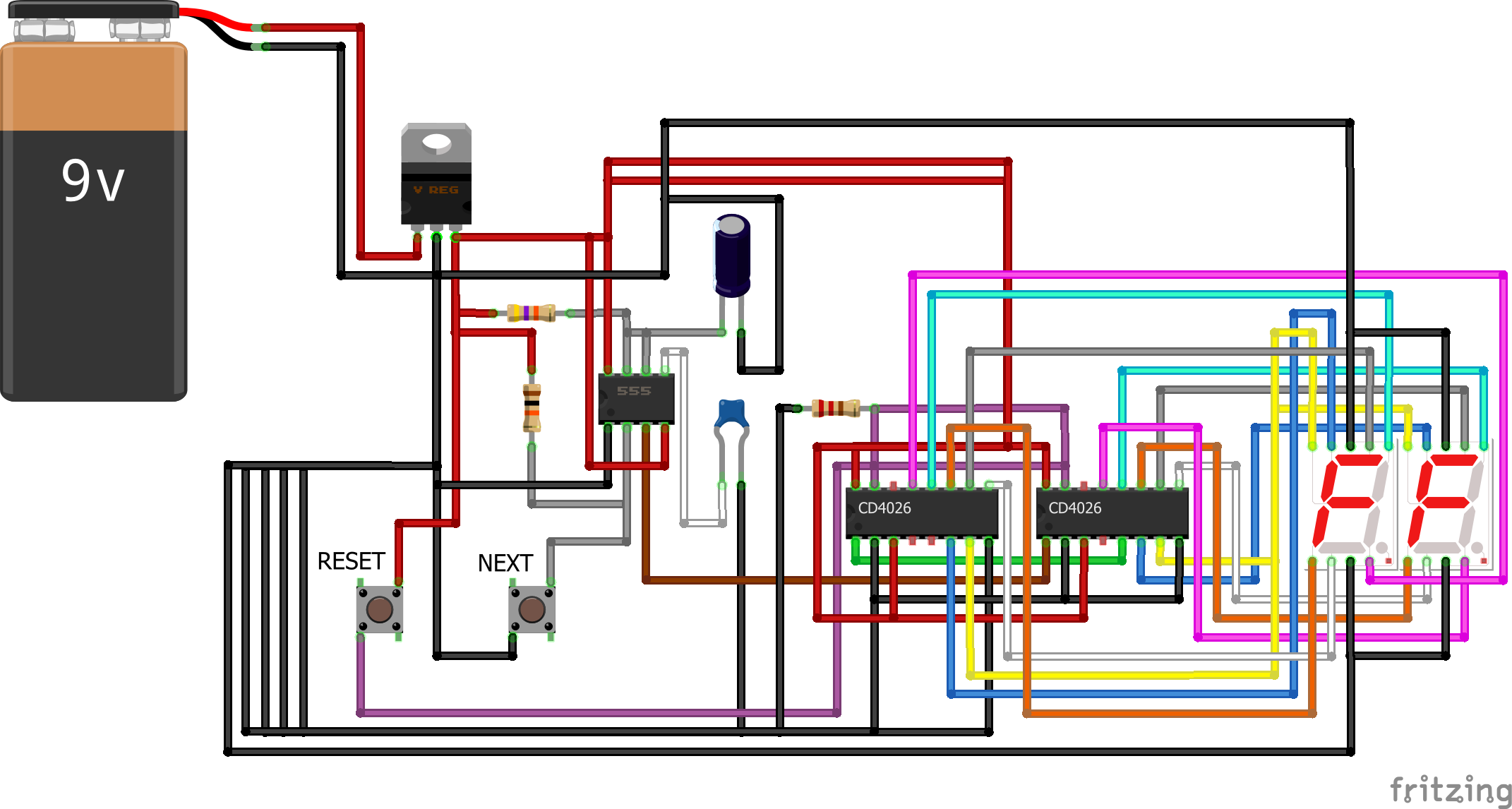
Fritzing Diagram
How It Works
When the circuit powers on, the LM7805 provides a regulated 5V supply to the main logic circuit. This stable voltage helps the NE555 and CD4026 ICs operate correctly. The capacitors support the power section by reducing voltage noise and helping prevent unstable behavior.
The NE555 timer generates a clock pulse. Each pulse acts like a signal that tells the CD4026 to count one step. If the circuit uses a manual button for the clock input, pressing the button can send one pulse at a time. If the NE555 runs automatically, the counter can advance repeatedly based on the timer speed.
The first CD4026 receives the pulse and updates the ones digit. It also sends the correct signals to the 7-segment display so the display shows the current number. The CD4026 removes the need to manually wire separate logic gates for each number. It already includes counting and display-decoding functions in one IC.
The second CD4026 handles the tens digit. When the ones digit completes a full cycle, the tens digit can advance. This is how the circuit becomes a two-digit counter instead of a single-digit counter. The displays work together to show values like 00, 01, 02, and so on up to 99.
The reset button brings the count back to zero. When pressed, it clears the CD4026 counters so the displays return to the starting value. This is useful when restarting the count or testing the circuit. The reset function also helps during troubleshooting because it confirms whether the counter ICs can return to a known state.
The 7-segment displays show the final output. Each number appears by lighting the correct LED segments. The CD4026 controls which segments turn on for each digit. This makes the output easy to read and gives the project a clear visual result.
Applications and Extensions
This 2 Digit Digital Counter can be used as a basic tally counter. It can count button presses, small events, objects, or simple pulses from another circuit. Because it displays the value directly, users can see the count without needing a computer or Serial Monitor. This makes it useful for beginner electronics demonstrations.
The project can also be used as a scoreboard counter. With a few changes, the buttons can increase or reset the score. This can be used for small games, classroom activities, or booth displays. The two-digit display makes it easy to show numbers clearly.
Another possible use is an object counter. A sensor can replace or trigger the manual count input. For example, an IR sensor or limit switch can send a pulse when an object passes. The CD4026 circuit can then count each detected object and show the total on the displays.
You can extend the project by adding more digits. Adding another CD4026 and another 7-segment display can turn it into a 3-digit counter. More stages can be added if the project needs a higher count range. This makes the circuit scalable for larger counting systems.
You can also improve the project by adding a better enclosure. Mount the two 7-segment displays in front, place the reset and next buttons below, and hide the ICs and wiring inside a case. This makes the counter easier to use and better for presentation. A clean enclosure also protects the breadboard wiring from being moved accidentally.
For advanced versions, you can add automatic and manual count modes. One switch can choose whether the NE555 timer controls the count or the push button controls it. You can also add a pause button to stop the counter temporarily. These upgrades make the project more flexible and useful for different demonstrations.
Watch the Full Demo Video
Here’s the 2 Digit Digital Counter
