
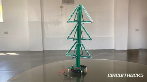
Want to build a Christmas-themed electronics project that lights up and plays music? 🌲✨ The 3D Flash RGB Christmas Tree DIY Kit is a soldering project that forms a standing Christmas tree using PCB branches, RGB LEDs, and a controller board. Once assembled and powered, the tree lights flash automatically and the music feature can play a simple tune. The PDF guide describes the kit as a 3D RGB music Christmas tree made from circuit boards and LEDs, designed to create a festive display for Christmas events, celebrations, and parties.
This project is different from basic LED blinking circuits because the final output becomes a decorative object. The PCB pieces do not only hold the components; they also form the tree structure. After soldering the branches, controller board, LEDs, switches, buzzer, and battery box, the project becomes a standing RGB display. It is a good build for users who want to practice soldering while creating something they can display.
The kit runs on DC 4.5V to 5.0V and can be powered through a DC 3.5mm power socket or a 3×AA battery box. The manual also lists a working current of 500mA and an installed size of 153 × 153 × 315mm, making it a medium-sized display project rather than a small breadboard test.
Why Build?
This project is worth building because it combines soldering practice, LED effects, music output, and 3D assembly in one kit. Many beginner electronics projects stay flat on a breadboard or PCB, but this one becomes a shaped Christmas tree. That makes the result more satisfying because the circuit also works as decoration.
It also helps beginners understand component placement and polarity. The guide emphasizes checking component direction, avoiding short circuits, installing LEDs correctly, and making sure all parts are in the right place before powering the kit. These habits are important for any soldering project, especially when the circuit includes many LEDs and transistor stages.
Another reason to build this kit is that it gives a clear visual reward after assembly. When the power is connected, the Christmas tree begins flashing automatically and the music function can play simple music. This makes the project easy to test because the LEDs and buzzer immediately show whether the build is working.
The project is also useful for holiday displays, school activities, booth decorations, and soldering workshops. It teaches electronics skills while producing a finished festive item. Because the final output has lights, structure, and sound, it feels more complete than a simple component exercise.
What You’ll Learn
By building this 3D Flash RGB Christmas Tree DIY Kit, you’ll learn:
- How to assemble a 3D PCB structure from multiple tree branch boards.
- How to identify PCB labels, alignment marks, and solder pads.
- How to solder resistors, capacitors, diodes, transistors, switches, LEDs, and a buzzer.
- How to check LED polarity before soldering.
- How to distinguish LED anode and cathode using lead length, flat edge, and PCB markings.
- How RGB LEDs can create a decorative flashing light effect.
- How a music chip and passive buzzer can add sound to a display project.
- How a battery box or DC power socket can power a small electronics kit.
- How to avoid common soldering issues such as reversed parts, cold joints, and short circuits.
- How to test the circuit after assembly and check whether the LEDs light correctly.
What You’ll Need
Assembly Guide
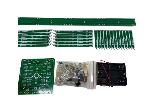
For the detailed assembly process, users can download and follow the full manual included with the 3D Flash RGB Christmas Tree DIY Kit. Since this project includes many PCB branch pieces, RGB LEDs, polarized parts, controller-board components, and final tree alignment steps, it is better to use the official visual guide while soldering. The manual shows how to separate and align the PCB brackets, identify LED positive and negative pins, install the RGB LEDs, place the resistors, capacitors, diodes, transistors, switches, buzzer, music chip, battery box, and mount the tree body to the controller board. Before powering the kit, users should carefully check the solder joints, component direction, LED polarity, battery wiring, and the required DC 4.5V to 5.0V working voltage.
How It Works
The project works by combining an RGB LED display circuit with a simple music circuit. The PCB branches hold the RGB LEDs in a tree shape, while the controller board manages the power and supporting components. Once the correct voltage is applied, the LEDs begin flashing automatically, creating the colorful Christmas tree effect.
The controller board includes several transistor stages. The component list shows multiple S9014 transistors and one S8050 transistor, which support the switching sections of the circuit. The kit also includes a PX088A music chip and a 5V passive buzzer, which provide the simple music effect when enabled.
The switches allow control over the kit’s functions, including the music feature. The PDF lists two self-locking switches and describes the kit features as including music enable/disable and automatic RGB LED flashing.
Power can come from the battery box or the DC power socket. The manual states that the kit accepts the correct working voltage from either the 3.5mm power socket or the battery box. Once powered correctly, the Christmas tree starts blinking and the music function starts automatically.
Applications and Extensions
This project works well as a holiday decoration for desks, classrooms, shops, booths, and home displays. The RGB LEDs create a colorful effect, while the music output adds a festive feel. Since the installed shape is a standing Christmas tree, it can be displayed directly after assembly.
It can also be used as a soldering practice kit. The build includes many common through-hole components, such as resistors, capacitors, diodes, transistors, switches, LEDs, a buzzer, and a power socket. This makes it useful for beginners who want to improve soldering accuracy and component identification.
The project can be extended by improving the display base. You can place the finished tree on a small platform, add a label, or create a protective acrylic cover. These upgrades can make the kit safer to transport and more attractive for presentations.
For a more creative version, users can customize the outer display setup. The tree can be placed inside a holiday diorama, gift box base, or event booth decoration. Since the kit already produces light and sound, improving the housing can make the final output look more polished.
Watch the Full Demo Video
Here’s the 3D Flash RGB Christmas Tree DIY Kit.