
Have you ever planned a project with lots of sensors, then realized your Arduino has nowhere to plug them all?
That moment is normal, especially when you start adding knobs, light sensors, IR modules, and extra “just one more” inputs.
A 16-channel analog multiplexer solves that problem in a clean way, because it lets one Arduino input read many signals by switching them one at a time.
With a CD74HC4067, you can build bigger input projects without jumping to a larger board, and you can keep your wiring neat instead of spreading wires across every pin.
Think of the CD74HC4067 like a smart rotary switch you control with four Arduino pins.
You tell it which channel you want, it connects that channel to a shared output called SIG, and your Arduino reads SIG as if the sensor were wired directly.
Nothing “magical” happens to the signal; the chip simply routes one input through a switch network.
That is why this part is useful for beginners: the idea is simple, the wiring is repeatable, and the same pattern works whether you read two sensors or sixteen.
This tutorial is written to help you move from “I know it exists” to “I can use it in real builds.”
You will start with a small test that reads two channels, because that is the fastest way to verify your wiring and understand how switching feels.
Then you will expand the same pattern into a full scan approach, so you can scale to 16 channels with confidence.
Along the way, you will also learn what causes unstable readings, what “wrong channel order” looks like, and how to fix the most common mistakes without guessing.
Why Build?
A multiplexer is one of the easiest ways to escape the “pin limit” trap without changing your whole project plan.
Instead of switching to a Mega, you can stay on an Uno or Nano and still read many inputs in an organized way.
That matters when you want to keep your build small, cheap, and easy to replace, especially for school projects or quick prototypes.
It also helps you reuse the same code base on different boards, because you are not locked into a board with many analog pins.
A second reason is wiring sanity, which becomes a real issue when you go beyond a few sensors.
When sensors are scattered across many Arduino pins, your wiring becomes harder to label, harder to trace, and harder to fix when one sensor stops working.
With a CD74HC4067, many sensor wires land in one place, and only a few wires go back to the Arduino.
This layout makes your project easier to document, easier to teach, and much easier to troubleshoot when you come back to it after a week.
The third reason is that multiplexing teaches you a reusable input “rhythm” that applies to many electronics tasks.
You select a source, allow a short moment for signals to settle, take a reading, and repeat in a loop.
That same pattern shows up in sensor scanning, keypad matrices, and even some display driving methods.
Once you learn this rhythm, reading many inputs feels natural, and your projects stop being limited by the number of pins on your board.
What You’ll Learn
By building this Arduino Analog Multiplexer, you’ll:
- What the CD74HC4067 does and when it is the right tool to use.
- How S0 – S3 select a channel using a 4-bit number from 0 to 15.
- What SIG is, and why SIG can feed one Arduino analog pin for many inputs. How to read two channels first, then scale into a full 16-channel scan.
- How to handle signal settling so readings do not look jumpy after switching.
- How to spot common wiring mistakes, like swapped channel order or missing ground.
- How to treat digital-type outputs through the mux (they look like near 0 or near 1023). What limits to respect so you do not damage the mux or the Arduino input.
What You’ll Need
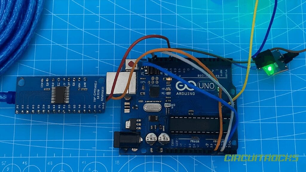
Fritzing Diagram
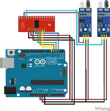
MUX:
- VCC → 5V
- GND → GND
- SIG → A0
- EN → GND
- S0 → D2
- S1 → D3
- S2 → D4
- S3 → D5
IR Proximity Obstacle:
- VCC → 5V
- GND → GND
- OUT → C1 and C2
Sample Code
The best beginner test is to read only two channels and print both values in one Serial line.
This keeps your output readable and makes it easy to compare the behavior of two sensors side by side.
If you twist potentiometer #1, you should see the value labeled C1 change, while C2 stays mostly steady, and vice versa.
If you use two digital-style sensor outputs, you should see values jump near 0 and near 1023 when the sensor toggles.
To make the selection clear, your code needs two helper functions: one to set the select pins, and one to read the chosen channel.
The selection function writes the four bits of the channel number to S0 – S3.
The read function selects the channel, waits a few milliseconds, then does analogRead(A0).
This keeps your loop clean and prevents copy-pasted code blocks from turning into a mess later.
Here is a clean starter sketch you can use for the two-channel test:
// CD74HC4067 (16-Channel Analog MUX) Test: Read C1 and C2 on one SIG pin

// MUX select pins
const int S0 = 2;
const int S1 = 3;
const int S2 = 4;
const int S3 = 5;

// MUX SIG pin -> Arduino A0
const int SIG_PIN = A0;

// Select which channel (0–15) is connected to SIG
void selectChannel(byte ch) {
  digitalWrite(S0, ch & 0x01);         // bit0
  digitalWrite(S1, (ch >> 1) & 0x01);  // bit1
  digitalWrite(S2, (ch >> 2) & 0x01);  // bit2
  digitalWrite(S3, (ch >> 3) & 0x01);  // bit3
}

// Read a selected channel through SIG
int readMuxChannel(byte ch) {
  selectChannel(ch);
  delay(5);                 // let signal settle
  return analogRead(SIG_PIN);
}

void setup() {
  Serial.begin(9600);

  pinMode(S0, OUTPUT);
  pinMode(S1, OUTPUT);
  pinMode(S2, OUTPUT);
  pinMode(S3, OUTPUT);

  Serial.println("CD74HC4067 Testing: Reading C1 and C2");
}

void loop() {
  int valC1 = readMuxChannel(1);  // C1
  int valC2 = readMuxChannel(2);  // C2

  Serial.print("C1: ");
  Serial.print(valC1);
  Serial.print("\tC2: ");
  Serial.println(valC2);

  delay(200);
}
How It Works?
Inside the HP4067 sit tiny electronic switches. When you set a number on S0 – S3, the chip connects that C pin to SIG. The Arduino reads SIG, so it receives the value from that one selected sensor. Because only one path is active, the signal stays clear.
For analog reading, wire SIG → A0 and choose a channel in code. Next, wait a few milliseconds so the node can settle. Then call analogRead(A0) and store or print the result. This approach fits sliders, light sensors, and other voltage sources.
For digital reading, wire SIG → a digital pin such as D8. After selecting a channel and a brief settle, call digitalRead(D8) and check for HIGH or LOW. Many IR obstacle boards read LOW when an object is present, so invert the logic if needed. With that, you can scan several digital modules through a single pin
Troubleshooting Guide
If you see no change at all, start with the simple checks that catch most issues.
Confirm that SIG really goes to A0, and confirm that VCC and GND on the mux board are correct.
If your sensors have their own power, confirm they share ground with the Arduino.
Also confirm EN/E is enabled (often tied to GND) so the mux is not silently disabled.
If values are noisy or jumpy even when the sensor is steady, focus on the signal settling and wiring quality.
Try increasing the settle delay from 5 ms to 10 ms, and see if the readings calm down.
Keep wires short and avoid routing SIG alongside motor wires or noisy power lines.
If your sensor output is weak, reading twice and keeping the second read can help, because the first read often captures the switching transient.
If the “wrong channel” seems to respond, you probably mixed up the channel pin order.
This happens a lot when people wire C1 and C2 but then label their wires the opposite way.
The mux does not know “left” or “right,” it only knows channel numbers, so your wiring order defines meaning.
A simple fix is to swap the two channel wires or update your labels so the code and physical layout match.
Applications & Extensions
Create a sensor panel for music, art, or classrooms. For example, map 12 knobs to MIDI, or read a grid of LDRs for a light wall. Because the wiring is compact, setup stays approachable.
Test robot sensors without using many pins. You can route several IR modules through the MUX and save the remaining pins for motors and servos. Then, log detections to Serial and tune thresholds with confidence.
Add upgrades as you grow. Show live bars on an OLED, trigger alarms at set levels, or stream scans to the Serial Plotter. If you need simultaneous sampling or higher precision later, add another MUX on a second pin or step up to a multi-channel ADC.
Frequently Asked Questions
What does this Arduino Analog Multiplexer tutorial cover?
Running out of pins? Imagine reading 16 sensors with only one Arduino input.
What Arduino library does the Arduino Analog Multiplexer tutorial use?
The sketch uses standard Wire.h (I2C) or SPI.h plus a part-specific library installable via Arduino IDE → Sketch → Include Library → Manage Libraries. See the Sample Code section.
Why does the Arduino Analog Multiplexer act differently on USB power vs battery?
Battery voltage sags under load. Add a 100uF cap across the rails, use a 5V/2A regulator-backed pack, and never power motors from the Arduino's onboard regulator.